MAINTENANCE PROCEDURE
MAINTENANCE
4-76
CLEAN HYDRAULIC TANK STRAINER
4
WARNING
q
The parts and oil are at high temperature immediately after the engine is stopped, and may cause
burns. Wait for the temperature to go down before starting the work.
q
When removing the oil filler cap, turn it slowly to release the internal pressure, then remove it.
1.
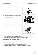
Remove the cap from oil filler (F), and release the internal
pressure.
2.
Remove 4 bolts, then remove cover (1). When doing this,
cover (1) may fly out under the force of spring (2), so keep
the cover pressed down while removing the bolts.
3.
Hold the top of rod (3) and pull up to remove spring (2) and
strainer (4).
4.
Remove all the dirt stuck to strainer (4), then wash it in
flushing oil. If strainer (4) is damaged, replace it with a new
part.
5.
When installing, insert strainer (4) into protruding part (5) of
the tank, and assemble.
6.
Assemble so that the protruding part at the bottom of cover
(1) holds spring (2), then tighten with the bolt.
CHECKING CHARGE PRESSURE OF NITROGEN GAS IN ACCUMULATOR (FOR CON-
TROL CIRCUIT)
4
WARNING
The accumulator is charged with high-pressure nitrogen gas, so mistaken operation may cause an explo-
sion, which will lead to serious injury or damage. When handling the accumulator, always do as follows.
The pressure in the hydraulic circuit cannot be completely removed. When removing the hydraulic equip-
ment, do not stand in the direction that the oil spurts out when carrying out the operation. In addition,
loosen the bolts slowly when carrying out the operation.
Do not disassemble the accumulator.
Do not bring it near flame or dispose of it in fire.
Do not make holes in it or weld it.
Do not hit it, roll it, or subject it to any impact.
When disposing of the accumulator, the gas must be released. Please contact your Komatsu distributor to
have this work carried out.
NOTICE
If the nitrogen gas charge pressure in the accumulator is low and operations are continued, it will become
impossible to release the remaining pressure inside the hydraulic circuit if a failure occurs on the
machine.
Содержание PC450-8
Страница 2: ......
Страница 3: ...FOREWORD 11 ...
Страница 66: ...SAFETY MAINTENANCE INFORMATION SAFETY 2 42 ...
Страница 267: ...MAINTENANCE 14 WARNING Please read and make sure that you understand the SAFETY section before reading this section ...
Страница 351: ...SPECIFICATIONS 15 ...
Страница 355: ...SPECIFICATIONS SPECIFICATIONS 5 5 6 7m Boom PC450 8 ...
Страница 356: ...SPECIFICATIONS SPECIFICATIONS 5 6 6 7m Boom PC450LC 8 ...
Страница 357: ...SPECIFICATIONS SPECIFICATIONS 5 7 6 7m Boom PC450LCHD 8 ...
Страница 359: ...SPECIFICATIONS SPECIFICATIONS 5 9 7 0m Boom PC450 8 ...
Страница 360: ...SPECIFICATIONS SPECIFICATIONS 5 10 7 0m Boom PC450LC 8 ...
Страница 410: ...SUPER LONG FRONT BOOM AND ARM ATTACHMENTS ANDD OPTIONS 6 50 ...
Страница 436: ...OPERATION HIGH REACH DEMOLITION EQUIPMENT 27M 7 26 3 Extend arm cylinder Arm cylinder ...
Страница 469: ...INDEX 18 ...
Страница 470: ...INDEX 8 2 ...
Страница 473: ...COLOPHON 18 ...


