Reassembly
122
62 690 05 Rev. E
KohlerEngines.com
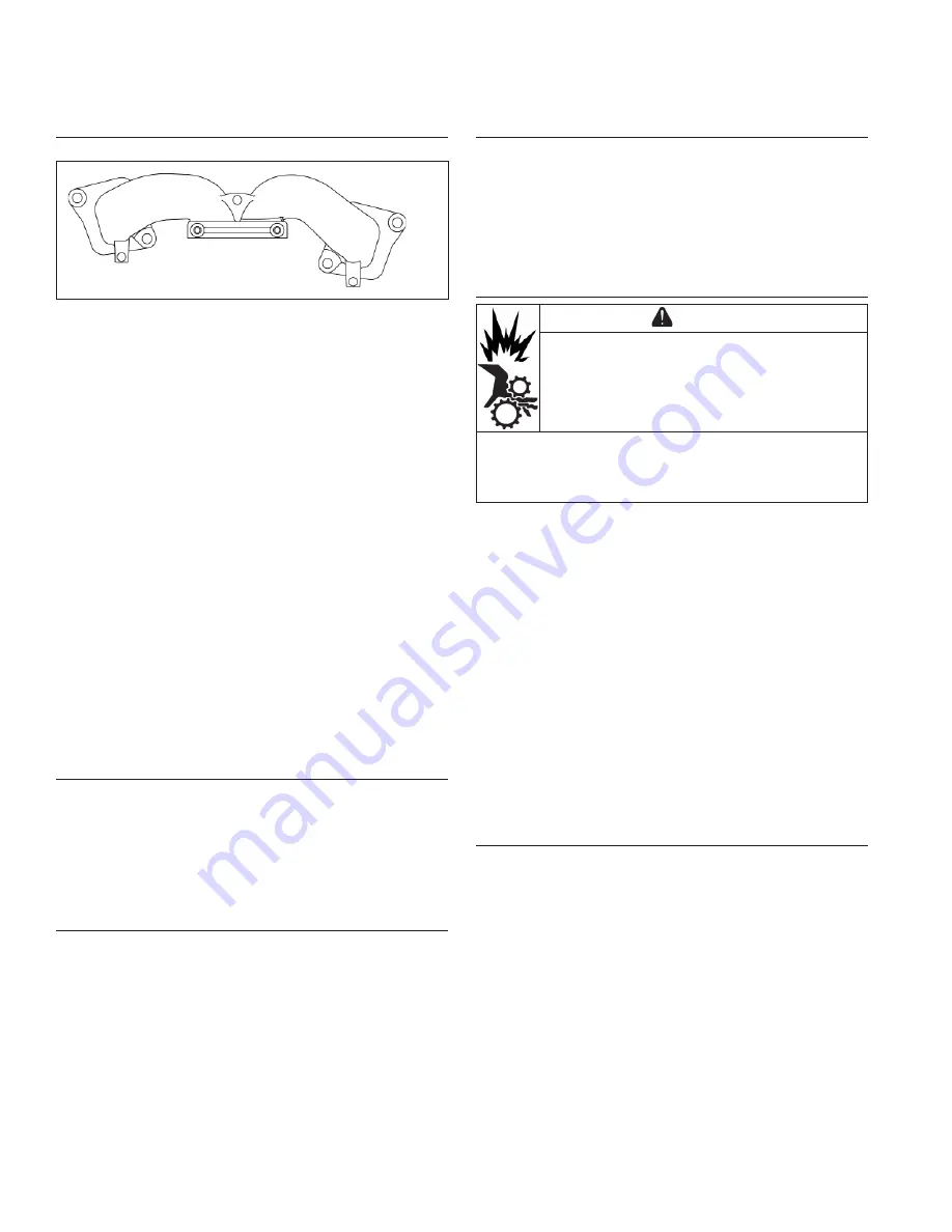
Install Intake Manifold/Throttle Body//Air Cleaner/
Backing Shroud Assembly
Intake Manifold Torque Sequence
3
1
2
4
1. Install new intake manifold gaskets on bolts so
notched section is inward and points toward fl ywheel
side. Loosely assemble intake manifold to heads; do
not tighten as this time.
2. Set backing shroud assembly onto crankcase and
start mounting screws. Torque screws in a crisscross
pattern to 10.7 N·m (95 in. lb.) into new holes, or 7.3
N·m (65 in. lb.) into used holes.
3. Apply pipe sealant with Tefl on
®
(Loctite
®
PST
®
592™
Thread Sealant or equivalent) to stator mounting
holes.
4. Position stator, aligning mounting holes so leads are
at bottom and toward rectifi er-regulator mount on
cylinder 1 side.
5. Install and torque screws to 9.3 N·m (82 in. lb.).
6. Check that stator wires are under molded clips in
backing shroud assembly.
7. Install dipstick tube with a new lower O-ring into
crankcase. Secure with lower mounting screw.
Torque screw to 7.7 N·m (68 in. lb.). Start upper
screw but do not tighten until after blower housing is
installed.
8. Torque intake manifold screws in 2 stages using
sequence shown, fi rst to 16.9 N·m (150 in. lb.),
fi nally to 22.6 N·m (200 in. lb.).
Install Breather Hose
1. Lightly oil lower end of breather hose and install into
hole in breather assembly. Cover should be situated
between 2 raised rings of hose.
2. Connect Oil Sentry
™
lead (green wire).
3. Install oil temp sensor connector.
4. Install MAP or TMAP sensor connector.
Install Oil Cooler
NOTE: New hose clamps are recommended for
reassembly, or if clamps have been loosened
(expanded) several times to avoid leakage.
1. Connect hoses between oil fi lter adapter and oil
cooler. Secure with new clamps.
2. Align oil cooler with bosses in backing shroud
assembly. Secure with screws and washers but do
not tighten at this time.
Install Ground Lead and Rectifi er-Regulator
Connector
1. Attach ground lead to outer rectifi er-regulator
mounting screw and washer, then torque mounting
screw to 2.5 N·m (22 in. lb.).
2. Install wiring harness clamp mounting bracket with
harness ground lead to inboard #1 side cylinder
boss.
3. Install rectifi er-regulator connector.
Install Flywheel
CAUTION
Damaging Crankshaft and Flywheel can
cause personal injury.
Using improper procedures can lead to broken
fragments. Broken fragments could be thrown from
engine. Always observe and use precautions and
procedures when installing fl ywheel.
NOTE: Before installing fl ywheel make sure crankshaft
taper and fl ywheel hub are clean, dry, and
completely free of any lubricants. Presence of
lubricants can cause fl ywheel to be over
stressed and damaged when screw is torqued to
specifi cations.
NOTE: Make sure fl ywheel key is installed properly in
keyway. Flywheel can become cracked or
damaged if key is not properly installed.
1. Install woodruff key into crankshaft keyway. Make
sure key is properly seated and parallel with shaft
taper.
2. Set fl ywheel/fan assembly onto crankshaft, being
careful not to shift woodruff key.
3. Install screw and washer.
4. Use a fl ywheel strap wrench or holding tool to hold
fl ywheel. Torque screw to 69.8 N·m (51 ft. lb.).
Install Fan (Style B)
NOTE: Position locating tabs on back of fan into locating
holes of fl ywheel.
1. Install fan onto fl ywheel using screws (engines with
plastic grass screen). Engines with a metal grass
screen will leave fan loosely assembled.
2. Torque screws to 9.9 N·m (88 in. lb.).


