


TP-6694
9/20
75
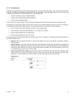
2.7.12 Analog Inputs
Displays the selected programming user-defined analog notice, warning, and shutdown inputs. These inputs provide a multitude
of choices for configuring customized auxiliary inputs. See the figure titled: Analog and Digital Inputs for a list of analog input
choices. For descriptions of the inputs listed refer to the following sections:
System Fault Warning Lamp with Digital Displays
System Fault Shutdown Lamp with Digital Displays
Status and Notice Digital Displays
There is an optional 2 input/5 output (I/O) module board available that can provide two additional analog (or digital) inputs.
The displays for analog inputs appear as shown below and have an acceptable operating range (0-5 VDC). The analog input
selection typically requires entering four values
—low warning, high warning, low shutdown, and high shutdown.
AIn A1 (analog input A1) standard (reserved and not user programmable)
AIn A2 (analog input A2) standard (Identified as A1 on SiteTech™ software)
AIn B1 (analog input B1) with I/O module board
AIn B2 (analog input B2) with I/O module board
All analog input selection and setup adjustments are done using SiteTech™ software. The following terms and descriptions are
part of the setup procedure.
Enabled.
This menu indicates whether or not the input is enabled. If the input is not enabled, the controller will ignore
this input signal.
Inhibit Time Delay.
The inhibit time delay is the time period following crank disconnect during which the generator set
stabilizes and the controller does not detect the fault or status event. The controller will ignore the input until the inhibit
time expires. If the inhibit time is set to zero, the input is monitored at all times, even when the generator is not running.
The inhibit time delay range is from 0 to 60 seconds.
Time Delay (shutdown or warning).
The time delay follows the inhibit time delay. The time delay is the time period
between when the controller first detects the fault or status event and the controller warning or shutdown lamp
illuminates. The delay prevents any nuisance alarms. The time delay range is from 0 to 60 seconds.
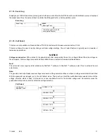
Analog Inputs
Analog - - >
Inputs
AIn A1
#####
AIn B1
#####
AIn B2
#####
Содержание APM402
Страница 6: ...6 TP 6694 9 20 ...
Страница 16: ...16 TP 6694 9 20 ...
Страница 42: ...42 TP 6694 9 20 ...
Страница 78: ...78 TP 6694 9 20 ...
Страница 112: ...112 TP 6694 9 20 ...
Страница 120: ...120 TP 6694 9 20 ...
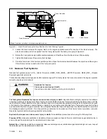
Страница 124: ...124 TP 6694 9 20 Figure 54 20 150 kW Permanent Magnet Single Phase Alternators ADV 5875AB 1 ...
Страница 125: ...TP 6694 9 20 125 Figure 55 20 300 kW Permanent Magnet Alternators ADV 5875AB 2 ...
Страница 126: ...126 TP 6694 9 20 Figure 56 60 IMS 300 kW Wound Exciter Field 20 300 kW 600 V Perm Magnet Alternators ADV 5875AB 3 ...
Страница 127: ...TP 6694 9 20 127 Figure 57 300 kW and Larger Pilot Excited Permanent Magnet 4M 5M 7M 10M Alternators ADV 5875AB 4 ...
Страница 128: ...128 TP 6694 9 20 ...
Страница 131: ...TP 6694 9 20 131 Figure 61 Battery Charger to Controller Connections DEC 3000 Controller ...
Страница 153: ...TP 6694 9 20 153 Figure 90 Controller Wiring Connections GM78246G 1 ...
Страница 154: ...154 TP 6694 9 20 Figure 91 Controller Wiring Connections GM78246G 2 ...
Страница 171: ......


