


TP-6694
9/20
107
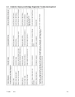
3.10.3 Specific Gravity Check
Use a battery hydrometer to check the specific gravity of the electrolyte in each battery cell of batteries with filler caps. Holding
the hydrometer vertically, read the number on the glass bulb at the top of the electrolyte level or the number adjacent to the
pointer. If the hydrometer used does not have a correction table, consult Figure 51.
Figure 51
Specific Gravity Temperature Correction
Determine the specific gravity and electrolyte temperature of the battery cells. Locate the temperature in Figure 51 and correct
the specific gravity by the amount shown. The battery is fully charged if the specific gravity is 1.260 at an electrolyte temperature
of 26.7°C (80°F). Maintain the specific gravities between cells within ±0.01 of each other. Charge the battery if the specific gravity
is below 1.215 at an electrolyte temperature of 26.7°C (80°F).
Note:
Some battery testers have four or five beads in a test tube. Draw electrolyte into the tube as with the battery hydrometer described
in this section or use the manufacturer’s instructions. Use Figure 52 to interpret typical test results.
Number of Floating Beads
Battery Condition
5
Overcharged
4
Fully Charged
3
A good charge
1 or 2
A low charge
0
A dead charge
Figure 52 Bead-Type Test Interpretation
Correction
Example No. 1
Temperature below 26.7°C (80°F)
Hydrometer Reading 1.250
Acid Temperature - 6.7°C (20°F)
Subtract .024 Specific Gravity
Corrected Specific Gravity is 1.226
1.250 - .024 = 1.226
Example No. 2
Temperature above 26.7°C (80°F)
Hydrometer Reading 1.235
Acid Temperature 37.8°C (100°F)
Add .008 Specific Gravity
Corrected Specific Gravity is 1.243
1.235 + .008 = 1.243
The temperature correction amounts to about .004 (4 points) of
specific gravity for each 5.5°C (10°F) change in temperature.
Содержание APM402
Страница 6: ...6 TP 6694 9 20 ...
Страница 16: ...16 TP 6694 9 20 ...
Страница 42: ...42 TP 6694 9 20 ...
Страница 78: ...78 TP 6694 9 20 ...
Страница 112: ...112 TP 6694 9 20 ...
Страница 120: ...120 TP 6694 9 20 ...
Страница 124: ...124 TP 6694 9 20 Figure 54 20 150 kW Permanent Magnet Single Phase Alternators ADV 5875AB 1 ...
Страница 125: ...TP 6694 9 20 125 Figure 55 20 300 kW Permanent Magnet Alternators ADV 5875AB 2 ...
Страница 126: ...126 TP 6694 9 20 Figure 56 60 IMS 300 kW Wound Exciter Field 20 300 kW 600 V Perm Magnet Alternators ADV 5875AB 3 ...
Страница 127: ...TP 6694 9 20 127 Figure 57 300 kW and Larger Pilot Excited Permanent Magnet 4M 5M 7M 10M Alternators ADV 5875AB 4 ...
Страница 128: ...128 TP 6694 9 20 ...
Страница 131: ...TP 6694 9 20 131 Figure 61 Battery Charger to Controller Connections DEC 3000 Controller ...
Страница 153: ...TP 6694 9 20 153 Figure 90 Controller Wiring Connections GM78246G 1 ...
Страница 154: ...154 TP 6694 9 20 Figure 91 Controller Wiring Connections GM78246G 2 ...
Страница 171: ......


