TP-6694
9/20
53
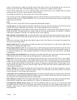
Volts L3- N: x.x V
Current L1: x.x A
Current L2: x.x A
Current L3: x.x A
The user can individually calibrate the values above or reset all of them. The local display
Reset all calib? No or Yes
. Select No
to make no changes and exit GenSet Calibration. Select Yes to reset all of the values.
When calibrating voltage, the metered value and the number being entered as the calibrated value must be within 10% of the
system operating voltage.
When calibrating current, the metered value must be at least 25% of the rated current on units smaller than 100 kW and at least
50 amps on units rated larger than 100 kW. The number being entered as the calibrated value must be within 10% of the metered
value.
Measurement Units (User Defined).
This selectable display is in the GenSet System Menu allowing the user to choose between
Metric and English displays. Use the Pushbutton/Rotary Selector Dial to navigate and select this feature. Changes to this display
can be done with the generator set running or stopped. The local display shows
Meas Units: Metric or Meas Units: English
.
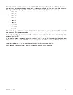
NFPA 110 Alarm Active.
This notice message indicates that the alarm for NFPA 110 is active. The fault lamp illuminates yellow
(warning) or red (shutdown), the alarm horn sounds, and the units shuts down (if a shutdown fault is detected) when the NFPA
110 fault signals the controller. The local display shows the respective fault message. The NFPA 110 faults include:
Battery charger fault
EPS supplying load
High battery voltage
High coolant temperature shutdown
High coolant temperature warning
High engine speed
Low battery voltage
Low coolant level
Low coolant temperature warning
Low fuel (level or pressure)
Low oil pressure shutdown
Low oil pressure warning
Master switch not in auto
Overcrank
Remote Start.
This status indicates that the generator set start circuit was closed from a remote location allowing the engine to
crank and run. The remote location is typically a set of contacts on a transfer switch or remote start switch. The local display
shows
Remote Start Status
.
System Ready.
This status indicates that the generator set is in the AUTO mode and available to start if the start circuit is
closed. The local display shows
System Ready
.
System Timer Failed.
This notice indicates that the controller timer logic has failed to time out a designated function. The local
display shows
Timer Error Notice
.
Voltage Regulator Adjustment (User Defined).
This feature is in the Voltage Regulator Menu allowing the user to fine adjust
the output voltage. Use the Pushbutton/Rotary Selector Dial to navigate and select this feature. Changes to this display must be
done with the generator set running. The local display shows
Enter volt reg? No or Yes
. Select No to exit the voltage regulator
menu. Select Yes to change the local display
VR Volt Adj: xxx.x V
.
Содержание APM402
Страница 6: ...6 TP 6694 9 20 ...
Страница 16: ...16 TP 6694 9 20 ...
Страница 42: ...42 TP 6694 9 20 ...
Страница 78: ...78 TP 6694 9 20 ...
Страница 112: ...112 TP 6694 9 20 ...
Страница 120: ...120 TP 6694 9 20 ...
Страница 124: ...124 TP 6694 9 20 Figure 54 20 150 kW Permanent Magnet Single Phase Alternators ADV 5875AB 1 ...
Страница 125: ...TP 6694 9 20 125 Figure 55 20 300 kW Permanent Magnet Alternators ADV 5875AB 2 ...
Страница 126: ...126 TP 6694 9 20 Figure 56 60 IMS 300 kW Wound Exciter Field 20 300 kW 600 V Perm Magnet Alternators ADV 5875AB 3 ...
Страница 127: ...TP 6694 9 20 127 Figure 57 300 kW and Larger Pilot Excited Permanent Magnet 4M 5M 7M 10M Alternators ADV 5875AB 4 ...
Страница 128: ...128 TP 6694 9 20 ...
Страница 131: ...TP 6694 9 20 131 Figure 61 Battery Charger to Controller Connections DEC 3000 Controller ...
Страница 153: ...TP 6694 9 20 153 Figure 90 Controller Wiring Connections GM78246G 1 ...
Страница 154: ...154 TP 6694 9 20 Figure 91 Controller Wiring Connections GM78246G 2 ...
Страница 171: ......


