


TP-6694
9/20
19
1.2.2
Annunciator Lamps
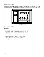
The controller has a single annunciator fault lamp providing visual generator set status. In addition, each button has a
corresponding lamp. See Figure 3.
Lamp/Button
Lamp color
Alarm (Fault) Lamp
Yellow (Warning) or Red (Shutdown)
Off/Reset Button
Red
Auto Button
Green (System Ready)
Run Button
Yellow
Alarm Silence/Lamp Test Button
Yellow
Figure 3
Annunciator Lamps
System Status Lamps (Master Control Switches)
The green lamp illuminates on the master control switch AUTO (automatic start) button indicating the system senses no faults
and the unit is ready to start by remote command.
The red lamp illuminates on the master control switch OFF/RESET button indicating the generator set is stopped.
The yellow lamp illuminates on the master control switch RUN button indicating the generator set is cranking or running from a
local command.
Only one of the three master control switch lamps will illuminate at any given time.
Alarm Silence Lamp.
Yellow lamp illuminates indicating the alarm horn was silenced.
(System) Fault Lamp.
Yellow lamp illuminates indicating a warning condition or red lamp illuminates indicating a shutdown
condition. See System Warning Fault Lamp and System Shutdown Fault Lamp following for system fault conditions.
System Warning Fault Lamp.
Yellow lamp identifies an existing fault condition that does not shut down the generator set. A
continuing system warning fault condition may cause a system shutdown. Correct all system warnings as soon as practical.
See the section titled: System Fault Warning Lamp with Digital Displays, for definitions of the items listed. The following
conditions cause a system warning:
AC sensing loss
Auxiliary input (analog or digital)
Battery charger communication loss
Battery charger fault
†
*
Note:
Optional input sensors not required with charger GM87448.
Battery charger identity conflict
Battery charger parameter mismatch
Battery fault
Common warning
Critical high fuel level (diesel-powered models only) *
Default parameters loaded
ECM diagnostics (multiple engine inputs)
Fuel tank leak (diesel-powered models only) *
Ground fault *
High battery voltage
High coolant temperature
Содержание APM402
Страница 6: ...6 TP 6694 9 20 ...
Страница 16: ...16 TP 6694 9 20 ...
Страница 42: ...42 TP 6694 9 20 ...
Страница 78: ...78 TP 6694 9 20 ...
Страница 112: ...112 TP 6694 9 20 ...
Страница 120: ...120 TP 6694 9 20 ...
Страница 124: ...124 TP 6694 9 20 Figure 54 20 150 kW Permanent Magnet Single Phase Alternators ADV 5875AB 1 ...
Страница 125: ...TP 6694 9 20 125 Figure 55 20 300 kW Permanent Magnet Alternators ADV 5875AB 2 ...
Страница 126: ...126 TP 6694 9 20 Figure 56 60 IMS 300 kW Wound Exciter Field 20 300 kW 600 V Perm Magnet Alternators ADV 5875AB 3 ...
Страница 127: ...TP 6694 9 20 127 Figure 57 300 kW and Larger Pilot Excited Permanent Magnet 4M 5M 7M 10M Alternators ADV 5875AB 4 ...
Страница 128: ...128 TP 6694 9 20 ...
Страница 131: ...TP 6694 9 20 131 Figure 61 Battery Charger to Controller Connections DEC 3000 Controller ...
Страница 153: ...TP 6694 9 20 153 Figure 90 Controller Wiring Connections GM78246G 1 ...
Страница 154: ...154 TP 6694 9 20 Figure 91 Controller Wiring Connections GM78246G 2 ...
Страница 171: ......


