


TP-6694
9/20
65
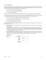
To enable calibration, start the generator set and select the
Volts L1-L2 display
. Then push and hold the pushbutton/rotary
selector dial until the
Calibration Enabled
popup appears. Calibration of each display is now available. The display will show the
following values for three-phase generator sets. Single-phase generator sets will only display items marked (*).
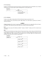
Volts L1-L2 *
Volts L2-L3
Volts L3-L1
Volts L1-N *
Volts L2-N *
Volts L3-N
Current L1 *
Current L2 *
Current L3
The user can change individual values or can select
Reset Calib?
- Yes to reset all voltage and current values. The
Reset Calib?
display will only show if calibration is enabled.
When calibrating voltage, the metered value and the number being entered as the calibrated value must be within 10% of the
system operating voltage.
When calibrating current, the metered value must be at least 25% of the rated current on units smaller than 100 kW and at least
50 amps on units rated larger than 100 kW. The number being entered as the calibrated value must within 10% of the metered
value.
To disable calibration, Rotate the pushbutton/rotary selector dial until the
<- Return
popup appears.
Momentarily press the pushbutton/rotary selector dial. Stop the generator set if not already done.
Содержание APM402
Страница 6: ...6 TP 6694 9 20 ...
Страница 16: ...16 TP 6694 9 20 ...
Страница 42: ...42 TP 6694 9 20 ...
Страница 78: ...78 TP 6694 9 20 ...
Страница 112: ...112 TP 6694 9 20 ...
Страница 120: ...120 TP 6694 9 20 ...
Страница 124: ...124 TP 6694 9 20 Figure 54 20 150 kW Permanent Magnet Single Phase Alternators ADV 5875AB 1 ...
Страница 125: ...TP 6694 9 20 125 Figure 55 20 300 kW Permanent Magnet Alternators ADV 5875AB 2 ...
Страница 126: ...126 TP 6694 9 20 Figure 56 60 IMS 300 kW Wound Exciter Field 20 300 kW 600 V Perm Magnet Alternators ADV 5875AB 3 ...
Страница 127: ...TP 6694 9 20 127 Figure 57 300 kW and Larger Pilot Excited Permanent Magnet 4M 5M 7M 10M Alternators ADV 5875AB 4 ...
Страница 128: ...128 TP 6694 9 20 ...
Страница 131: ...TP 6694 9 20 131 Figure 61 Battery Charger to Controller Connections DEC 3000 Controller ...
Страница 153: ...TP 6694 9 20 153 Figure 90 Controller Wiring Connections GM78246G 1 ...
Страница 154: ...154 TP 6694 9 20 Figure 91 Controller Wiring Connections GM78246G 2 ...
Страница 171: ......


