


TP-6694
9/20
39
Description
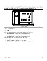
Controller
Display
Message
Alarm
Horn
Fault
Lamp
Warning
Shutdown
Write
Access
Display
SiteTech
GenSet
Mode
Always
Running
Stopped
Range
Setting
Default
Selection
Time
Delay
Range
(sec.)
Default
Time
Delay
(sec.)
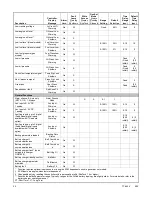
Charger Depleted Battery
Voltage Target
S
4
–12
(12 V)
18
–24
(24 V)
10
(12 V)
20
(24 V)
Charger Equalize Stage
Duration (Min)
Note:
Equalize is only available with
FLA/VRLA topology selected.
S
A
60
–480
Charger Manual Equalize
Cycle Activation
Note:
Equalize is only available with
FLA/VRLA topology selected.
S
A
Active
Inactive
Inactive
Charger Maximum Absorption
Time Threshold (Min.)
S
A
60
–360
60
–600
(NiCad
only)
240
Charger Maximum Bulk Time
Threshold (Min)
S
A
6
–600
480
Charger Refresh Charge
Cycle Time (Hr)
S
A
0,
23
–672
335
Charger Return To Bulk State
Voltage Threshold (V)
S
A
10
–13
(12 V)**
20
–26
(24 V)**
12.8
(12 V)
25.6
(24 V)
Charger Starter Battery
Topology
Note:
Verify that the battery topology
is set correctly for the battery
type that is used.
Incorrect charger output
system voltage may cause
irreversible damage to the
battery and abnormal out
gassing.
S
A
Default
FLA/
VRLA
AGM
Gel
NiCad
Default
Charger System Battery
Voltage
Note:
Verify that the system
voltage is set correctly for
the battery type that is used.
Incorrect charger output
system voltage may cause
irreversible damage to the
battery and abnormal out
gassing.
S
A
System
12 VDC
System
24 VDC
12 VDC
Charger Temperature
Compensation Enable
S
A
Active
Inactive
Inactive
Charger Temperature
Compensation Slope (mV/ C)
S
A
-40
–0
(12 V)
-80
–0
(24 V)
-30
(12 V)
- 60
(24 V)
* Function requires optional input sensors or is engine ECM dependent on some generator set models.
† ECM inputs are engine-manufacturer dependent.
‡ Changeable only by resetting the controller with a personality profile (SiteTech 1.4 or higher).
** Denotes the default parameter range. Typically, ranges for the NiCad battery topology are slightly wider. For more details, refer to the
battery charger operation manual.
ST- Short Term, LT- Long Term
Содержание APM402
Страница 6: ...6 TP 6694 9 20 ...
Страница 16: ...16 TP 6694 9 20 ...
Страница 42: ...42 TP 6694 9 20 ...
Страница 78: ...78 TP 6694 9 20 ...
Страница 112: ...112 TP 6694 9 20 ...
Страница 120: ...120 TP 6694 9 20 ...
Страница 124: ...124 TP 6694 9 20 Figure 54 20 150 kW Permanent Magnet Single Phase Alternators ADV 5875AB 1 ...
Страница 125: ...TP 6694 9 20 125 Figure 55 20 300 kW Permanent Magnet Alternators ADV 5875AB 2 ...
Страница 126: ...126 TP 6694 9 20 Figure 56 60 IMS 300 kW Wound Exciter Field 20 300 kW 600 V Perm Magnet Alternators ADV 5875AB 3 ...
Страница 127: ...TP 6694 9 20 127 Figure 57 300 kW and Larger Pilot Excited Permanent Magnet 4M 5M 7M 10M Alternators ADV 5875AB 4 ...
Страница 128: ...128 TP 6694 9 20 ...
Страница 131: ...TP 6694 9 20 131 Figure 61 Battery Charger to Controller Connections DEC 3000 Controller ...
Страница 153: ...TP 6694 9 20 153 Figure 90 Controller Wiring Connections GM78246G 1 ...
Страница 154: ...154 TP 6694 9 20 Figure 91 Controller Wiring Connections GM78246G 2 ...
Страница 171: ......


