


38
C35-VAV
39
C35-VAV
Symptom
Diagnostic Test
Cause
Solution
Scheduler is not working
properly
Set new timers and test the
scheduler. The home screen
should respond in line with
the set timetable.
Time and or Date have not
been set correctly.
Enter the correct date and
time in the Date Time menu.
(Page 19).
When device is following
scheduler it is always in
standby mode
The scheduler timer presets
have not been configured.
Enter new timers in
scheduler presets.
System is not heating or
cooling to the desired set
point.
Check the home screen
status bar to ensure the
correct control sequence icon:
(heating) or
(cooling), is present.
The unit is set to manual
changeover and is in the
incorrect control mode
Enter the Menu and press
the (heating) or
(cooling) button for manual
changeover.
Manual changeover can’t be
performed from the settings
menu.
Check if the (heating)
or (cooling) button is
unavailable (dimmed button).
Manual changeover is
disabled. Manual changeover
is only possible when Control
sequence is set to “Heating
or Cooling” and if Sensor
function in In/Out menu is
not set to “Changeover”.
Change the Sensor function
in In/Out menu or Control
sequence in Advanced
Parameters.
Sensor function in In/Out
menu can’t be changed.
Check if the message on the
button is “Not connected”.
If the PT1000 sensor is not
connected to RTD terminals
or if the resistance of
connected element is less
than 780Ω and more than
1500Ω then the Sensor
function parameter will be
unavailable.
Connect the correct RTD
sensor (PT1000) to RTD
terminals.
Setpoint buttons are not
shown on the Home screen.
Check if the device is in
Economy or Standby mode by
reading the status on screen.
Setpoints in these modes
can only be adjusted in the
setpoints menu.
Change the Operating mode
with button or bypass to
Comfort mode by activating
Occupied mode function with
button.
System is not heating or
cooling and only the Menu
button is shown on the
Home screen.
Check if “Window is open”
message is shown on the
display and if any window in
the room is open.
The device has detected that
a window is open .
Device will exit bypass mode
when the window is closed.
“Window is open” message is
shown on the display and all
windows are closed.
Close or open the window to
see if the device will change
operating mode.
Polarity of the window
contact is not correct.
Change the Window contact
polarity in In/Out menu.
The device does not
communicate over the
BACnet MS/TP network.
Inspect wires and wall
mounts for signs of damage.
Disconnected/broken/
damaged wire.
Repair or install new wiring
where necessary.
The device does not
communicate over the
BACnet MS/TP network.
Count the number of devices
on the network segment
The maximum number
of devices on a network
segment has been exceeded.
Install a BACnet router to
extend the BACnet data bus
network.
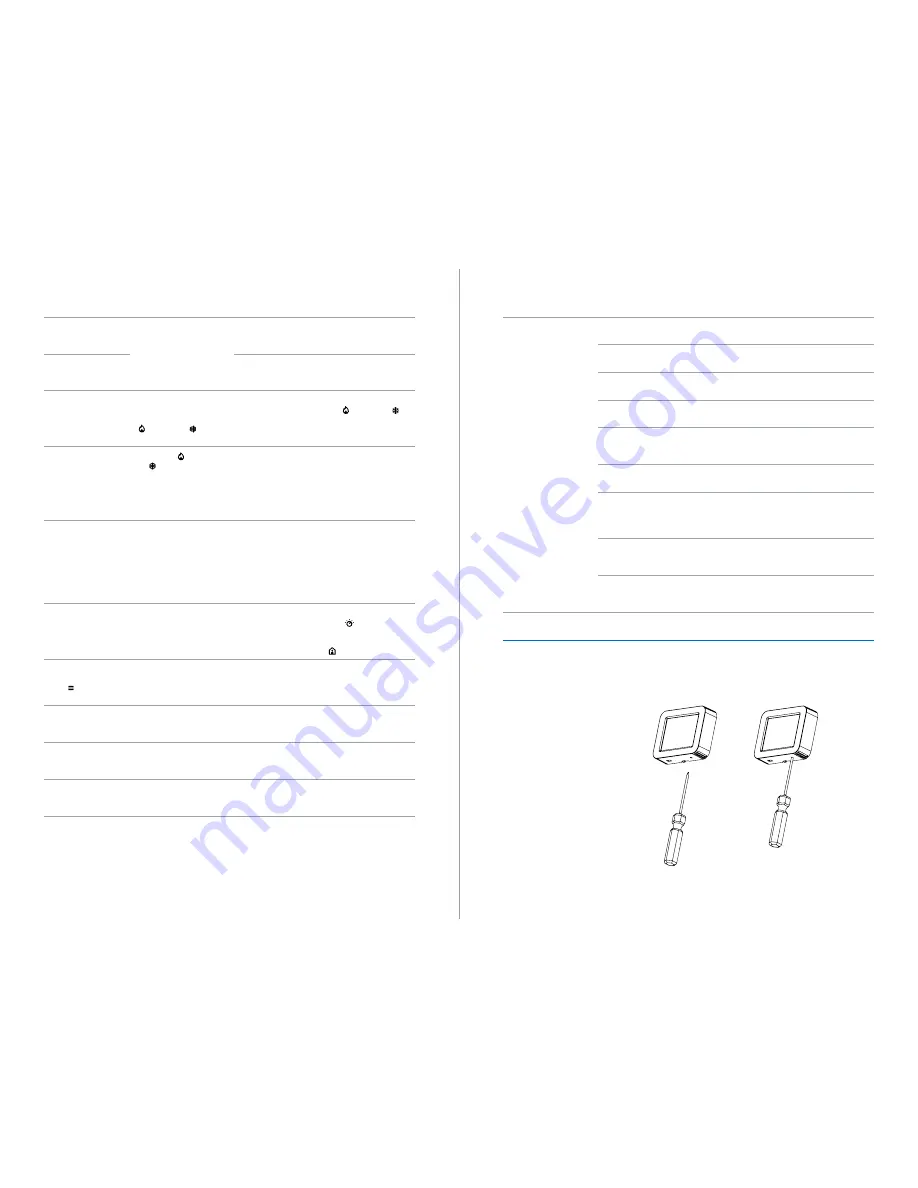
20. Device Reset
In the event C35-VAV becomes inoperative, the device can be reset using the manual
reset switch which is located on the bottom right hand corner of the device. Gently insert
a thin object into the opening. The device should reboot through the normal boot menu.
Note: Do not touch the display during the boot menu to avoid inadvertently performing a
factory reset.
Figure 20.1.
Symptom
Diagnostic Test
Cause
Solution
The device does not
communicate over the
BACnet MS/TP network.
Check the device ID in the
network settings menu.
Two or more devices have the
same device ID .
Assign unique ID to every
device on network.
Check the MAC address in the
network settings menu.
Two or more devices have the
same MAC address.
Assign unique MAC address to
every device on data bus.
Check the Baud rate in the
network settings menu.
The correct baud rate has not
been configured.
Set the same baud rate to all
devices on data bus.
Check the connection
terminals on the wall mount.
BACnet data bus polarity has
been incorrectly connected .
Rewire the D+ and D- signal
wires to correct polarity.
Check the Max Master
parameter in the network
settings menu.
The Max Master parameter
has been incorrectly
configured.
Set the Max Master to
highest MAC address used on
data bus.
Measure the power supply
voltage on device terminals.
Incorrect voltage is being
supplied to the device.
Connect correct voltage to
device.
Check if cable termination
is enabled on first and last
device on the data bus.
Incorrect signal levels are
being received by the data
bus.
Enable termination by
connecting termination jumper
on first and last device on data
bus.
Check if all devices are
connected in daisy-chain
topology .
The network has not been
correctly wired.
Connect all devices only in
daisy-chain topology.
Determine the cable length
for furthest device.
Network cable length is too
long.
Ensure the total wire length
for the furthest device does
not exceed 1200 meters.
CODIS35v4.4
WEIGHT:
A4
SHEET 1 OF 1
SCALE:1:2
DWG NO.
TITLE:
REVISION
DO NOT SCALE DRAWING
MATERIAL:
DATE
SIGNATURE
NAME
DEBUR AND
BREAK SHARP
EDGES
FINISH:
UNLESS OTHERWISE SPECIFIED:
DIMENSIONS ARE IN MILLIMETERS
SURFACE FINISH:
TOLERANCES:
LINEAR:
ANGULAR:
Q.A
MFG
APPV'D
CHK'D
DRAWN
CODIS35v4.4
WEIGHT:
A4
SHEET 1 OF 1
SCALE:1:2
DWG NO.
TITLE:
REVISION
DO NOT SCALE DRAWING
MATERIAL:
DATE
SIGNATURE
NAME
DEBUR AND
BREAK SHARP
EDGES
FINISH:
UNLESS OTHERWISE SPECIFIED:
DIMENSIONS ARE IN MILLIMETERS
SURFACE FINISH:
TOLERANCES:
LINEAR:
ANGULAR:
Q.A
MFG
APPV'D
CHK'D
DRAWN
Содержание C35-VAV...
Страница 23: ......


