MDC-5000 Series
Chapter 3 Installation method
0092653004-00
3-35
3.4.6 Cable connection for inter-switch
3.4.6.1 Cable connection instructions for cross-over, dual and independent
connection
In case of a dual, cross-over, or master/slave connection using two sets of radar system or
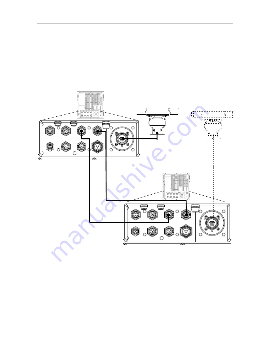
Processor unit, the remote cable and data cable are connected as shown in the figure 3.16.
(1) The heading, speed and latitude/longitude signals input to the data connector of master
Processor unit and are supplied to the slave Processor unit via data cable. The slave Processor
unit can also use TT (ATA) and chart option functions in the same way as the master one.
(2) Connect the slave Scanner unit to the slave Processor unit in a crossover connection.
(3) Operation unit (MRO-110) is required for MRM-110.
Figure 3.16 Connecting a slave Processor unit on
Crossover, dual and independent connection
Master Processor unit
(MRM-110)
J7
Slave Processor unit (MRM-110)
Connect slave antenna
unit to slave Processor unit
in the case of crossover
connection.
Remote cable
CW-561-10M or 30M
(10m or 30m)
J8
J8
J3
J3
Data cable
CW-373
Содержание MDC-5004
Страница 1: ......
Страница 2: ......
Страница 20: ...Chapter 3 installation method MDC 5000 Series 3 2 0092653004 00 RB808 RB809 Unit mm inch ...
Страница 88: ... This page intentionally left blank ...
Страница 114: ... This page intentionally left blank ...
Страница 130: ... This page intentionally left blank ...
Страница 150: ... This page intentionally left blank ...
Страница 151: ...0092653004 00 A 1 INTER CONNECTION DIAGRAM RB806 ...
Страница 152: ...A 2 0092653004 00 INTER CONNECTION DIAGRAM RB807 ...
Страница 153: ...0092653004 00 A 3 INTER CONNECTION DIAGRAM RB808 ...
Страница 154: ...A 4 0092653004 00 INTER CONNECTION DIAGRAM RB809 ...
Страница 155: ...0092653004 00 A 5 INTER CONNECTION DIAGRAM MRM 110 MRO 110 ...
Страница 156: ......


