background image

Chapter 3 Basic operation 

MDC-2200/2500 Series 


0093125002-04 

3-18 

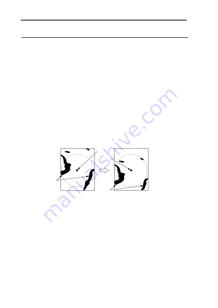
For relative motion (RM) and true motion (TM)


Relative motion indicates the motion of surrounding targets with own ship’s position fixed at the center 

of the screen.   

Because own ship position is centralized, fixed targets such as the land also move on the display while 

the ship is moving. 


True motion indicates the motion of the target as a center of the specified bearing. 

Fixed targets that do not move in any direction stay on the display as they were and actually moving 

targets move on the screen.   

*No true motion [TM] is available for [H UP] mode because the heading always continues to move.   


Relative motion (RM): The own ship position is fixed and the other surrounding targets move on the 

screen. 

This is useful for monitoring the surrounding situation from the own ship’s 

position as a center. 


Moving

Fixed

Own
ship

Moving

Land


Содержание MDC-2240

Страница 1: ......

Страница 2: ...ified body and is in conformity with the standards EN 60945 2002 Clauses 9 10 12 EN 62252 2004 Clauses 4 8 4 33 5 8 5 33 and Annex D ITU R Recommendation RM 1177 and complies with the essential requirements of Directive 1999 5 EC Conformity procedure under Annex IV of 1999 5 EC Technical Construction file has been undertaken by QinetiQ Ltd Cody Technology Park Ively Road Farnborough GU14 0LX Unite...

Страница 3: ...ified body and is in conformity with the standards EN 60945 2002 Clauses 9 10 12 EN 62252 2004 Clauses 4 8 4 33 5 8 5 33 and Annex D ITU R Recommendation RM 1177 and complies with the essential requirements of Directive 1999 5 EC Conformity procedure under Annex IV of 1999 5 EC Technical Construction file has been undertaken by QinetiQ Ltd Cody Technology Park Ively Road Farnborough GU14 0LX Unite...

Страница 4: ......

Страница 5: ......

Страница 6: ...mber version number If any contents of the document has been revised the version number is altered on the cover sheet and corresponding chapter revised while the other chapters remain unchanged The document number is designated lower right in the cover sheet and at the left or right part of every footer Prohibition of copy reprint No part of this manual shall be reprinted or copied by any means wi...

Страница 7: ...3 1 Power On 3 1 Power Off 3 1 3 2 Change brilliance of display unit Screen and Control panel 3 1 Change screen brilliance 3 1 Change brightness of control panel dimmer 3 2 3 3 Transmission 3 2 Start transmission 3 2 Stop transmission 3 3 3 4 Change range indicated distance 3 3 3 5 Adjust receiver gain GAIN 3 4 3 6 Reduce sea clutter STC 3 5 3 7 Reduce rain snosion pulse length SP LP 3 7 3 9 Enhan...

Страница 8: ...EPA operation method 3 25 Update EPA 3 26 Types and meaning of ATA EPA symbol 3 27 3 16 Use F Function key 3 28 For short cut menu 3 28 Position data output 3 29 Chapter 4 Menu operations 4 1 4 1 How to see and use Menu 4 1 Display menu main menu 4 1 Delete menu 4 1 Select menu item 4 1 Determine setting 4 2 Display detailed menu 4 2 4 2 MARKER menu 4 3 1 Display Range rings 4 3 2 Set bearing mode...

Страница 9: ...relative or true 4 11 4 Select trail color Blue or Red 4 13 5 Select trail display shape 4 13 6 Sustain range 4 13 7 Time keep 4 13 8 Switching of base input sensor in true motion Course or Position 4 13 9 Rel mode 4 14 10 Trail detection level 1 to 6 4 14 11 Interference rejection IR 4 14 12 Display target stable using signal processing 4 14 13 Switch over Day Night mode 4 15 14 Daytime Echo colo...

Страница 10: ...tup ATA buzzer sound 4 22 5 Setup AIS buzzer sound 4 22 6 Use Alarm 1 4 22 7 Setup Alarm 1 detection mode 4 24 8 Setup Alarm 1 detection level 4 24 9 Setup Alarm 1 area setting method 4 24 10 Use Alarm 2 4 24 11 Select Alarm 2 block number 4 24 12 Delete registered data by designating block number 4 25 13 Select Alarm 2 detection method 4 25 14 Setup Alarm 2 detection level 4 25 15 Input edit Alar...

Страница 11: ...hide chart 4 34 Insert method of C MAP chart card 4 34 Chart card removal 4 35 2 Setup own ship track ATA target track and AIS target track 4 35 3 Setup track memory interval 4 36 4 Delete track 4 36 5 Setup Way point route 4 36 6 Display mark 4 36 7 Select block number for mark display 4 36 8 Delete mark data of specified block number 4 37 9 Display line from own ship location to mark 4 37 10 Sel...

Страница 12: ...ARTUP menu 4 44 1 Tuning method 4 44 2 Auto tune setting 4 44 3 Manual tune setting 4 44 4 Bearing setting 4 44 5 Range adjustment 4 44 6 STC curve 4 45 7 Main Bang Suppression 4 45 8 9 10 F key setting 4 45 11 RAIN key setting 4 45 12 SEA key setting 4 45 13 GAIN key setting 4 45 4 11 I O menu 4 46 1 Heading bearing 4 46 2 Ship speed 4 46 3 COG SOG 4 46 4 Latitude longitude 4 46 5 Ground stabiliz...

Страница 13: ...itting hours 4 52 5 Panel test 4 53 6 Monitor 4 53 7 Monitor No selection 4 53 8 ATA diagnose 4 53 9 AIS diagnose 4 53 10 Version 4 53 4 16 ANTENNA menu 4 54 1 High voltage 4 54 2 Mag current 4 54 3 Mag heater voltage 4 54 4 Tune voltage 4 54 5 Antenna unit type 4 54 6 Antenna unit communication status 4 54 4 17 OPTION menu 4 55 1 Inter switch 4 55 2 Antennal location designation 4 55 3 Echo offse...

Страница 14: ...ad 4 60 4 19 Menu configuration 4 61 Chapter 5 Specification and configurations 5 1 5 1 Antenna 5 1 5 2 Display unit 5 1 5 3 Configuration items 5 2 Standard configuration 5 2 Options 5 2 5 4 External view and dimensions 5 3 Chapter 6 Principle of radar system 6 1 6 1 What is radar system 6 1 Side lobe 6 1 Beam width 6 2 6 2 Characteristics of radar radio wave 6 2 Target hardness reflected 6 2 Rad...

Страница 15: ... denotes that there is a risk of death or serious injury when not dealing with it correctly Caution Mark for caution This symbol denotes that there is a risk of slight injury or damage of device when not dealing with it correctly Mark for danger high voltage This symbol denotes that there is a risk of death or serious injury caused by electric shock when not dealing with it correctly Mark for proh...

Страница 16: ...ified power density and distance from the device in accordance with the provision as specified in IEC 60945 Model name Output power Antenna length 100W m2 10W m2 4kW 3 feet Antenna 0 9m 2 85m MDC 2240 MDC 2540 4kW 4 feet Antenna 1 01m 3 2m 6kW 4 feet Antenna 1 09m 3 46m MDC 2260 MDC 2560 6kW 6 feet Antenna 1 3m 4 10m 12kW 4 feet Antenna 1 55m 4 89m MDC 2210 MDC 2510 12kW 6 feet Antenna 1 84m 5 81m...

Страница 17: ...ily cause a disease of the respiratory system Be careful not to inhale dust Caution Caution against static electricity Please handle the printed circuit board only after taking measures against static electricity Static electricity occurs from the carpet on the floor of the cabin etc and clothes made of synthetic fiber and may damage the electronic parts on the printed circuit board ...

Страница 18: ...ntenna scanner unit with a transmit power of 4kW 6kW 12kW 25kW a display unit with a 15 inch color LCD display and operating panel unit The MDC 2240 2260 2210 2220 type Radar system is the system which consists of the antenna scanner unit with the transmit power 4kW 6kW 12kW 25kW and display unit with 12 1 inch color LCD display For this device its multi functions and high performance is accomplis...

Страница 19: ... screen if the radar is started up by factory default settings These alarms are disengaged by pressing OFF key temporarily however the alarms are activated again next time the radar is started up Disengage the alarm detection function on start up by the following setting Once set the alarm is not detected next time the radar is started up MENU DATADISP PROTECT CANCEL ENT MENU NAV STAB GND SEA ENT ...

Страница 20: ...P T H R N G W I D T H B R G GZ 000 0NM 000 0NM V R M 1 15 146N 139 45 037E 35 0 000NM 000 0 CURSOR AUTO Heading Tune Own ship speed Fixing of image Upper display Gain Anti sea clutter Anti rain clutter Interference rejection Enhance target Signal processing Cursor VRM Range RR interval TRAILS Off center Zoom X band TX pulse length Trail mode EBL VRM2 EBL2 EBL1 VRM1 Lower display Bearing scale Rang...

Страница 21: ...Chapter 2 Function and control names MDC 2200 2500 Series 0093125002 02 2 2 2 2 Control panel MDC 2500 Series MDC 2200 Series ...

Страница 22: ... knob This knob is used to adjust to reduce reflection of ripple of sea surface to improve target delectability Surface reflection reduction effect is increased by turning knob to the clockwise direction It is also used as function key by pressing knob 6 GAIN knob This knob is used to adjust receiving gain to improve target delectability Gain is increased by turning knob clockwise It is also used ...

Страница 23: ... ATA EPA or AIS and to select mark during mark display 14 POWER ON OFF key This key is used to turn power on or off 15 STBY TX key This key is used to switch on TX or standby 16 EBL knob Note EBL VRM knobs are common for MDC 2200 This knob is used to operate EBL or to adjust screen brilliance Offset function is activated when this knob is pressed 17 OFFSET lamp Note This function is not available ...

Страница 24: ... for MDC 2200 This knob is used to operate VRM or to adjust panel dimmer 25 SP LP key This key is used to change pulse length to improve target delectability 26 OFF CENT key This key is used to switch on or off Off center 27 MODE key Note This function is not available for MDC 2200 This key is used to switch over display mode such as Head up North up etc 28 OFF key Heading line is erased during th...

Страница 25: ...for longer than 3 sec IMPORTANT Re entry of power shall be performed after having passed for longer than 3 sec after power off 3 2 Change brilliance of display unit Screen and Control panel Change screen brilliance For MDC 2200 1 Press BRILL key Note Each time BRILL key is pressed it changes over Screen brilliance and Panel dimmer 2 Screen brilliance adjustment window is displayed 3 Turn EBL VRM k...

Страница 26: ...M knob counter clockwise to decrease brightness of the panel dimmer The panel dimmer changes in 5 steps each time by pressing EBL VRM knob Push Brighter Darker EBL VRM knob For MDC 2500 1 Press PANEL key 2 Panel dimmer adjustment window is displayed in the screen 3 Turn VRM knob clockwise to increase brightness of the panel dimmer Turn VRM knob counter clockwise to decrease brightness of the panel...

Страница 27: ... observing range is numerically displayed on the upper left of the screen 1 Press RANGE key to zoom out the area and to observe a long distance Press RANGE key to zoom in the area and to magnify proximity of own ship to observe Indicated distance 1 5 Bearing scale Range Own ship Ranges usable per each model are as shown below Standard setting Model name Range 0 125NM 0 25NM 0 5NM 0 75NM 1 5NM 3NM ...

Страница 28: ... according to observing status such as range of distance sea surface rain and snow clutter etc 1 Turn GAIN knob clockwise to increase receiving gain Turn GAIN knob counter clockwise to decrease receiving gain Up Down Gain Decrease gain to observe short range dense targets easier Increase gain effectively for long range targets however if gain is increased to much the noise will increase accordingl...

Страница 29: ...ecome hard to be observed By using SEA knob suppress this influence of anti sea clutter and adjust it to make targets easier to be observed 1 Turn SEA knob clockwise to increase anti sea clutter effect 2 Turn SEA knob counter clockwise to decrease anti sea clutter effect High Low Anti sea clutter The knob shall be turned to leftmost position in a calm environment This function reduces gain in shor...

Страница 30: ...ti rain clutter effect 2 Turn RAIN knob counter clockwise to decrease anti rain clutter effect Strong Weak Anti rain clutter The knob should be turned to leftmost position in normal environment Turning the knob clockwise profiles of targets which were hidden due to the echo of rain snow etc appear but pay attention not to fail to miss the small targets When a function to suppress ant rain and anti...

Страница 31: ...re suitable in that range will be changed each time by pressing key Current pulse length is shown upper left of the screen 3 9 Enhance target ENH This function is intended to enhance a desired target on the screen and make the image easier to be observed 1 Press ENH key Each time by pressing It switches over ENH1 ENH2 ENH 3 Off Enhance levels are ENH 1 small ENH 2 medium ENH 3 large Current select...

Страница 32: ...distance by turning VRM knob The value of distance display is the distance to the target Increace of range Decreace of range VRM knob 3 Press again the VRM1 key to turn VRM1 off The distance display in lower right of the screen is turned off simultaneously 4 Press VRM2 key to display the broken line circle of VRM2 Operation procedure and distance display are the same procedure as for VRM1 5 Both V...

Страница 33: ...BL1 060 5 Bearing cahnges by turning EBL knob Own ship Target bearing from own ship 2 By turning EBL knob align the electronic bearing line to the target to be measured The value of bearing display is the bearing of the target Clockwise Counter clockwise EBL knob 3 Press EBL1 key again to turn EBL1off 4 Press EBL2 key and EBL2 electronic bearing broken line will be displayed The operation procedur...

Страница 34: ...RKER SEL set up EBL2 VRM2 to the PI then press ENT key NAV ALARM CHART DATADISP STARTUP ECHO RANGE RINGS BRG TRUE REL CURSOR EBL2 VRM2 MARKER Move to the right PARALLEL INDEX PI ATA EPA MARKER SEL MARKER SEL is provided for MDC 2200 series onl Displayed at installation ofAIS unit optional AIS Move to the right y 2 Display line number setting Press MENU key to display Menu To proceed MARKER PARALLE...

Страница 35: ...s to be displayed Press MENU key to display Menu To proceed MARKER PARALLEL INDEX and select number of lines then press ENT key NAV ALARM CHART DATADISP STARTUP ECHO RANGE RINGS BRG TRUE REL CURSOR NORMAL MARKER Move to the right PARALLEL INDEX 1 2 3 4 5 6 7 ATA EPA MARKER SEL MARKER SEL is provided for MDC 2200 series onl Displayed at installation of AIS unit optional AIS Move to the right y In N...

Страница 36: ...NORMAL mode for the basic number of lines Increase of ditance Decrease of distance VRM knob Decrease of distance Increase of distance PI 000 0 2 500NM PI RE L PI 000 0 5 000NM PI RE L Rotate the EBL knob to change bearing Clockwise Counter clockwise EBL knob PI 040 0 3 000NM PI RE L Refer to Measure distance and bearing between two points Offset page 3 13 for offsetting the center of PI to optiona...

Страница 37: ...M displayed at lower part of the screen will change to blue For MDC 2500 The offset lamp color located at lower right under EBL knob will change to vermillion Push EBL knob Target A 331 5 EBL1 Target B Own ship position VRM1 1 424NM VRM1 EBL1 By operating Joystick the markers of EBL1 and VRM1 will move together with cross cursor Move Joystick Target A 331 5 EBL1 Target B Own ship position Cursor V...

Страница 38: ...U key to display Menu Select ECHO DAY NIGHT and select Day echo or Night echo color then press ENT key For MDC 2500 1 Press DAY NIGHT key to switch over Echo color to Day echo and Night echo alternatively The above can be operated by using Menu 3 12 Remove the heading line This function is used when a target is overlapped with a heading line and hard to be observed 1 Press OFF key to temporarily h...

Страница 39: ...on you want to move own ship by operating Joystick 2 Press OFF CENT key to move own ship to cross cursor position Own ship Own ship 3 Press OFF CENT key again to return own ship to the center of the screen Off center area is limited to 66 of the designated range 34 66 Own ship relocatable area Own ship Off center position can be fixed to stern orientation instead of cross cursor position Chapter 4...

Страница 40: ...ut of both bearing and speed signal to use C UP TM and N UP TM display mode For MDC 2200 1 Press MENU key to display Menu Select ECHO DISP MODE then select from H UP RM C UP RM C UP TM N UP RM N UP TM Display mode is shown on the upper left of the screen For MDC 2500 1 Press MODE key The display mode will be changed in the following order each time you press MODE key Current display mode is displa...

Страница 41: ...ing line is shown deviated accordingly from the setup course To navigate along the setup course ship handling shall be done to keep heading line displayed on direct top of the screen For N UP North up mode This mode always keeps displaying true north on the top of the screen It makes easy to consult with the chart because of the display oriented to a true north N Land Target 1 Target 2 Own ship He...

Страница 42: ... moving True motion indicates the motion of the target as a center of the specified bearing Fixed targets that do not move in any direction stay on the display as they were and actually moving targets move on the screen No true motion TM is available for H UP mode because the heading always continues to move Relative motion RM The own ship position is fixed and the other surrounding targets move o...

Страница 43: ...ets such as a land etc Moving Fixed Own ship Own ship Land 34 66 Own ship position relocatable area in TM Center of display Reset true motion When own ship position reaches to about 66 of effective screen radius own ship position is automatically reset to opposite orientation of the screen Moving toward the stern Own ship Own ship N N It is also possible to reset own ship position before it reache...

Страница 44: ... Closest Point of Approach Speed of the target Course of the target Vector of the target Heading bearing and speed input by optional GPS compass or equivalent is required to input to use ATA EPA function Object acquired and started tracking is called Target Item ATA EPA Manual acquisition Yes Yes Auto acquisition Yes No Tracking method Automatic Manual Max tracking number 50 50 ATA operation metho...

Страница 45: ...ed targets 1 Press MENU key to display Menu Select ATA EPA ALL DELETE and then press ENT key MARKER NAV ALARM CHART DETADISP STARTUP ECHO Move to the right AT A EPA AIS Displayed at installation of AIS unit optional ATA EPA TYPE ACQ DELETE ALL DELETE MAN ACQ NO AUTO DETECT TARGET ID TARGET SELECT EPA UPDATE DATA STYLE Use Automatic acquisition Up to 40 targets can be acquired in default 1 Press ME...

Страница 46: ...ng 3 Press EBL1 or EBL2 key and then change BRG WIDTH by using EBL knob In the same way Press VRM1 or VRM2 key and then change RNG DPPTH by using VRM knob In figure display on the lower left of the screen Item under setup is indicated by left mark 4 Setup process is completed by pressing ENT key after the area designation then auto acquisition starts To switch auto acquisition off display the same...

Страница 47: ...up by following procedure to fill background to ease to see data Press MENU key to display Menu Select DATADISP LOWER DISP BACK then set to ON 3 When 3 target data is displayed in the detail data display area When need to switch to display for more than 4 targets lay cursor on target to display then press ENT key Selected target data will be displayed in left display part Old data will be shifted ...

Страница 48: ...ode Relative vector display does not show real motion of the target but show relative motion to the own ship Target with its vector orientated to own ship is dangerous ship Accordingly true vector is used for grasping actual situation of target while relative vector to grasp CPA of target 3 CPA Closest point to approach setting MENU ALARM LIM CPA Setting value 0 0 to 19 9NM This item is to set clo...

Страница 49: ...d passed lay cross hair cursor on moved target then press ACQ key F2 key for MDC 2200 again Note When acquiring 2 or more target up to 50 select target number by using Menu then start operation The symbol moves to the latest target position and its course and speed are displayed by vector Up to 5 history track points are shown on the display with symbol ACQ key 3 As the symbol moves according to t...

Страница 50: ...rrected by using Joystick Wrong position 2 Press MENU key to display Menu Select ATA EPA EPA UPDATE and then press ENT key MARKER NAV ALARM CHART DETADISP STARTUP ECHO Move to the right AT A EPA AIS Displayed at installation of AIS unit optional ATA EPA TYPE ACQ DELETE ALL DELETE MAN ACQ NO AUTO DETEC T TARGET ID TARGET SELEC T EPA UPDATE DATA STYLE 3 Update tracking setup ...

Страница 51: ...splayed in steady tracking state Displayed at indicating numerical value after steady tracking Displayed when above steady tracking symbol has under run both specified CPA and TCPA value Displayed when above indicating numerical value symbol has under run both specified CAP and TCPA Displayed when the tracked target is out of tracking and then the alarm sounds Both display and sound disappear in 1...

Страница 52: ...L DELETE TARGET UPDATE CHART MARK OWN MARK CURSOR TLL OUT UPPER DISP VIDEO MODE SHORT CUT OFF MARKER NAV ALARM CHART DETADISP STARTUP ECHO Move to the right ATA EPA AIS Displayed at installation of AIS unit optional Move to the right 2 The same procedure as step 1 is applied for F2 KEY SET F3 KEY SET RAIN KEY SET SEA KEY SET and GAIN KEY SET by selecting each item and pressing the ENT key For shor...

Страница 53: ...o the position to output information then press TLL OUT of function key The data of cross cursor position will be output each time one presses function key Refer to Display detailed Menu Page 4 2 for Detailed Menu operation Input mark into own ship position or cross cursor position and output latitude longitude information 1 Select Detailed Menu I O OUTPUT J4 J5 TLL OUT MARK 2 Assign MARK OWN or M...

Страница 54: ...2 Sub menu is displayed by turning Joystick to the right after Main menu item is selected 3 Turn Joystick up or down to select sub menu item 4 Turn Joystick to the right after sub menu is selected then next sub menu will be displayed 5 Turn Joystick to the left to return previous menu Menu operating procedure NAV ALARM CHART DATADISP STARTUP ECHO RANGE RINGS BRG TRUE REL CURSOR ON MARKER Move to t...

Страница 55: ...sic menu operation is available in this menu Detailed menu is displayed by following operation 1 Press MENU key to display Main menu Select DATADISP PROTECT CANCEL and then press ENT key MARKER NAV ALARM CHART DETADISP STARTUP ECHO Move to the right ATA EPA AIS Displayed at installation of AIS unit optional UPPER DISP LOWER DISP BACK DISP 1 DISP 2 DISP 3 PROTECT CANCEL 2 Press MENU key again Then ...

Страница 56: ...DEX PI DISPLAY SIDE CURSOR VRM1 UNIT VRM2 UNIT PI UNIT STERN MRK CURSOR SHAPE TRACKING CURSOR HU MOVE VRM EBL CROSS SCALE CHARA CHARA POSI CHARA TYPE HL BRINK GUARD LINE OS OUTLINE OS PROFILE SHIP S PROFILE Shaded item are displayed in detailed menu OFF ON REL TRUE EBL2 VRM2 PI NORMAL 1 7 ONE BOTH OFF ON L L NM km sm RANGE LINK NM km sm RANGE LINK NM km sm RANGE LINK OFF ON Select cursor shape OFF...

Страница 57: ...rue bearing mode is switched to relative bearing mode when heading signal is intermitted 3 Marker selection MDC 2200 only Switch over operation mode of EBL2 VRM2 key EBL2 VRM2 or Parallel index can be selected Refer to Measure distance bearing PI Parallel index line Page 3 10 Parallel index is activated by pressing EBL knob for MDC 2500 4 Designate display lines of Parallel index Designate display...

Страница 58: ... key to stop latitude longitude display IMPORTANT Heading signal and latitude longitude signal shall be input to display latitude longitude Cursor display is turned off normally and when operated only with joystick cursor can also be displayed Display only when cursor is in use Select MARKER CURSOR OFF then press ENT key Select setting item ON then press ENT key to keep cursor displayed CURSOR 0 2...

Страница 59: ...ge of radar image is set 10 Display stern marker This function is to display marker in opposite side of heading line stern direction 11 Setting of cursor shape Cross cursor shape can be changed as desired Select out of 22 types of shape Lowest is hair line cursor which can be displayed up to extreme top bottom right and left of the screen 12 Tracking cursor Tracking cursor is the function to have ...

Страница 60: ... EBL2 are displayed at the same time the following symbol will be displayed mark at selected intersection mark for unselected intersection 15 Display bearing scale Display bearing scale on the outer circumference of effective radar screen mark is displayed intersection of heading line and bearing scale Bearing scale 16 Display bearing in numerical value or with symbol on the bearing scale Display ...

Страница 61: ...small target on the heading line 20 Display guard line This function is to display parallel lines to the heading on both side of own ship position Distance to guard line from own ship can be set at 0 to 10000m left and right side independently 21 Display own ship s outline Set up On Off of own ship s outline display 22 Setup own ship s profile Cannot use on transmitting Press MENU key to display M...

Страница 62: ...p s profile by using up to 50 lines Display own ship s profile ON OFF Profile setting X1 1000 to 1000m Y1 1000 to 1000m X2 1000 to 1000m Y2 1000 to 1000m Each line is designated by Start and End point based on antenna position Example 1m 1m 1m 5m 10m X1 Y1 X2 Y2 1 1 1 1 10 2 1 10 1 15 3 1 15 3 10 4 3 10 3 1 5 3 1 1 1 6 0 0 0 0 50 0 0 0 0 X1 Y1 denotes start point X2 Y2 denotes end point 1 Start En...

Страница 63: ...haded item is displayed in detailed menu 1 2 3 4 5 6 7 8 9 10 11 12 13 14 15 16 17 18 19 20 21 22 23 24 25 26 27 H UP RM C UP RM C UP TM N UP RM N UP TM OFF CONTINUE 30SEC 1MIN 3MIN 6MIN 12MIN 24MIN 48MIN TRUE REL BLUE RED OFF ON OFF ON COURSE POSITION HDG TRUE 1 6 OFF 1 2 3 4 5 OFF 1 2 3 DAY NIGHT WHITE YELLOW GREEN MULTI WHITE YELLOW GREEN MULTI Action Action OPPOSITE COURSE CENTER OFF 1 2 START...

Страница 64: ...UP RM N UP TM Display mode is displayed on upper left of the screen This operation can be performed by pressing MODE key on the panel for MDC 2500 Refer to 3 14 Select display mode 2 Display trail Display trail to get movement of the target Length of trail display is selected from CONTINUOUS 30SEC 1MIN 3MIN 6MIN 12MIN 24MIN and 48MIN No trail will be displayed when OFF is selected 3 Select trail d...

Страница 65: ...ength is equal to distance between own ship and other ship 1 it means that they will collide after 6 min Display mode N UP RM R N Other ship 1 Own ship 6min 6min Prospect of collision after 6 min True trail T Display trail of moving target with its course and speed independently from own ship s movement It is used to monitor course and speed of the target Fixed target such as land etc is not displ...

Страница 66: ...changed In case of ON if either trail function is set ON or trail time is changed the trail equivalent to the time set is displayed Movement of the other vessels traveling direction and speed can be captured instantly In case Time keep function is set ON the Alarm2 detection function cannot be used in the alarm menu Also selectable time of TRAILS menu are OFF CONTINUE 30s to 24hr 8 Switching of ba...

Страница 67: ...1 display trail even from weak image signal 6 display trail only from strong image signal IMPORTANT Lower detection level may display trail only in the position where target is not shown on the screen 11 Interference rejection IR Other ship s radar of the same frequency band may cause interference noise on the screen This interference effect is not uniform but in most cases spiral or radius shape ...

Страница 68: ...ground color 17 Night background color selection Change Night mode background color Select Night mode background color 18 Enlarge cursor position image by zooming function Zoom function enlarge image centered by cursor position in one step lower range It is used to observe surrounding situation of the target at cursor position in detail 1 Move cursor to the enlarged image position by operating cur...

Страница 69: ...nd end bearing of sector Sector scan 1 is the mode not to display image of designated bearing not suppress transmission to avoid reflection image such as from mast or other construction objects on the screen Sector scan 2 is the mode to stop transmission of the designated bearing and not to display image It is used to avoid transmission of radar wave to specific bearing 23 Designate range unit NM ...

Страница 70: ...rned off the display range of radar image will remain within effective radius only It is used to ease to see surrounding values such as numeral data around screen 27 Off center position Moving location of own ship position by operating off center can be set toward a cross cursor position default or a stern direction ...

Страница 71: ...for true motion TM of radar image and ATA AIS target bearing and speed 2 Set up tide bearing Compensate effect of tidal bearing when speed over water sensor is used for stabilization on GND 3 Set up tide speed Compensate effect of tidal speed when speed over water sensor is used for stabilization on GND 4 Set up vector display time Set up vector display time for ATA EPA AIS and own ship course Dir...

Страница 72: ...block in use Plural blocks can not be used simultaneously Navline can be used as simple drawing function by its alarm function being turned off refer to item 9 detection and being line display only 7 Select block no of navline Select block no of navline to be used 1 to 20 8 Delete navline by designating block no Delete navline data registered by latitude longitude Select block no to be deleted by ...

Страница 73: ...TA auto acquisition function and AIS information IMPORTANT ATA may not be recognized depend on reflection level of target In this case No danger mark is indicated on the target IMPORTANT Symbol is blinked in red when AIS target enters into guard zone area GUARD ZONE LIM CPA LIM TCPA ATA BUZZER AIS BUZZER ALARM 1 DETECT DETECT LVL AREA ALARM 2 DISP BLOCK NO BLOCK CLEAR DETECT DETECT LVL SETUP Shade...

Страница 74: ...L2 key RNG and DEPTH is switched over by pressing VRM1 key or VRM2 key Select BRG WIDTH RNG DEPTH then setup area by turning EBL knob and VRM knob Press ENT key after setup then setting is completed Removal of guard zone function Press MENU key to display Menu Select ALARM GUARD ZONE then press ENT key BRG DPT BRG 315 8 WDT 100 3 RNG 4 133NM DPT 0 755NM Guard zone BRG 315 8 WIDTH 100 3 BRG 315 8 W...

Страница 75: ... its course and its speed by EPA ATA AIS undergone the setup value of both CPA TCPA 4 Setup ATA buzzer sound Setup ATA buzzer OFF when alarm sound of operating ATA alarm by CPA TCPA alarm of lost target is not used 5 Setup AIS buzzer sound Setup AIS buzzer OFF when alarm sound of operating AIS is not used 6 Use Alarm 1 Alarm 1 displays alarm indication and generates alarm sound when target enters ...

Страница 76: ...tched over by pressing EBL1 key or EBL2 key 4 RNG and DEPTH are switched over by pressing VRM1 key or VRM2 key Select BRG WDT RNG DPT then setup area by using EBL knob and VRM knob 5 Press ENT key after setup to complete setting To delete Alarm1 function 6 Press MENU key to display Menu Select ALARM ALARM1 AREA then press ENT key BRG 315 8 WIDTH 100 3 BRG 315 8 WIDTH 100 3 RNG 4 133NM DEPTH 0 755N...

Страница 77: ...gh setting value will not respond to small target 9 Setup Alarm 1 area setting method Alarm1 area setting method select VARIABLE or FIXED Initial value is variable and refer to item 6 Use alarm1 for setting operation When fixed is set and also ALARM1 AREA is assigned to F Function key alarm area is switched over to Area1 90 Area2 180 Area3 360 by pressing F Function key 10 Use Alarm 2 Alarm2 setup...

Страница 78: ... figure by displaying the area of Alarm2 only 14 Setup Alarm 2 detection level This item is to setup signal level for target detection in the alarm setup area Setting value is 1 to 7 Small setting value responds to weak signal Large setting value responds to strong signal only Too low setting value responds to alarm even by noise Pay attention that too high value may not respond to weak target 15 ...

Страница 79: ...000E OFF LATITUDE LONGITUDE INPUT 1 LATITUDE LONGITUDE DIVIDE 1 35 00 000N 135 00 000E OFF 2 35 01 000N 135 01 000E OFF 3 35 02 000N 135 02 000E OFF 4 35 03 000N 135 03 000E OFF 5 35 04 000N 135 04 000E OFF 6 35 05 000N 135 05 000E OFF 7 35 06 000N 135 06 000E OFF 8 35 07 000N 135 07 000E OFF 9 35 08 000N 135 08 000E OFF 10 35 09 000N 135 09 000E ON 11 35 20 000N 135 20 000E OFF 12 35 21 000N 135 ...

Страница 80: ... be acquired by using Joystick Select acquisition menu then press ENT key Symbol is displayed on cursor position ˮ mark is displayed just after acquisition then changes to mark after about 30 seconds Target number is displayed near the target Manual acquisition can be performed easily by using ACQ key for MDC 2500 or Function key for MDC 2200 on the operation panel Refer to 3 15 Use ATA EPA 3 Sele...

Страница 81: ...up number of the targets to acquire manually Initial value is 10 targets When changes number to be acquired manually auto acquiring number is also changed at the same time 50 manual acquisition number auto acquisition number Note Auto acquisition function is not available when manual acquisition number is set to 50 6 Auto acquisition Set up auto acquisition area Refer to 3 15 Use ATA EPA 7 Set up ...

Страница 82: ...a display format Set up ATA EPA information display content to be displayed at lower part of the screen Select RNG BRG or LAT LON format IMPORTANT Refer to 4 9 DATADISP menu for data display method ATA CPA TCPA COG SOG T BRG RNG ATA EPA ATA CPA TCPA COG SOG LAT LON ATA EPA ...

Страница 83: ... then select ON and press ENT key MARKER NAV ALARM CHART DETADISP STARTUP ECHO Move to the right ATA EPA AIS AIS TARGET ID TARGET SELECT LIMIT LOST SLEEP Move to the right OFF ON 2 Set up target ID display Target ID can be displayed in AIS symbol on the screen Select target ID display from Number ship name both Number ship name Display OFF AIS TARGET ID TARGET SELECT LIMIT LOST SLEEP CLASS B ATON ...

Страница 84: ...ation Setup by range of 1 0NM to 64 0NM area from own ship Extension of detection area setting in crowded place may exceed 200 of maximum displayable number Pay attention if such case happened Overflow message is displayed and alarm is sounded and display of further other ships becomes unavailable 5 Setup lost target display Setup lost alarm display for lost target ON Display lost alarm and sound ...

Страница 85: ...ymbol overlapped to other ship based on obtained information Blink in 0 5 sec interval Alarm symbol Blink in 0 5 sec interval Normal symbol Meaning SLEEP Display of the ship not selected for information display It is displayed when it has under run the specified CAP or TCPA value It is drawn with a thick red line and the alarm sounds Display of out of track lost ship When the sleep ship becomes lo...

Страница 86: ...BUOY COAST LINE GPS BUOY Shaded display is displayed in detailed Menu 1 2 3 4 5 6 7 8 9 10 11 12 13 14 15 16 17 18 19 20 21 22 23 24 OFF ON 1 30 OFF DISP OWN ATA AIS OFF CONTINUE 15SEC 30SEC 1MIN 3MIN 6MIN 12MIN 1 30 CANCEL CLEAR OFF ON OFF ON 1 20 CANCEL CLEAR OFF ON Select mark shape from 18 types Input mark on own ship position Input mark on cursor position Input mark by latitude longitude OFF ...

Страница 87: ... or at some ranges This is because that there is no most appropriate chart information and not because of failure of the radar In those cases please try to change the range to get the chart Insert method of C MAP chart card 1 Open the lid located at right side of the radar screen and confirm loading slot Two loading slots are located No functional differences between two 2 Pay attention that card ...

Страница 88: ...nge without changing the range Set up each memory number 1 to 30 for using track record function OFF No memory and no display DISP Display only OWN Own ship track memory and display ATA ATA target track memory and display AIS AIS target track memory and display Trail display color and shape are as follows How to set own ship track 1 Select CHART PAST CRS 1 to 30 OWN then press ENT key 2 To discont...

Страница 89: ...isplay number and then execute deletion 5 Setup Way point route When waypoint route information is provided by GPS or by plotter it can be displayed on the radar screen as waypoint route Waypoint is displayed by mark in the screen Input sentence necessary for way point display is RMB or BWC Input sentence necessary for route display is RTE or WPL ID of Way point route can be displayed Refer to 20 ...

Страница 90: ...hod Move cursor to mark on the screen Press ENT key Line deletion method Move cursor to the mark of line to delete Press ENT key 10 Select display mark shape Select input mark shape out of 18 types When mark shape is changed after inputting mark it can be performed by using 13 latitude longitude input Menu 11 Input mark own ship position Proceed CHART OWN then press ENT key MARKER NAV ALARM CHART ...

Страница 91: ...key then select CHART CURSOR and press ENT key by keeping OFF key pressed In case of MARK OWN MARK CURSOR is assigned to F Function key 1 Move cursor onto mark to be deleted 2 Press F key by keeping OFF key pressed 13 Input edit mark latitude longitude input Input mark by latitude longitude With this menu mark data already registered can be edited Change shape Change latitude data Change longitude...

Страница 92: ...is used to accommodate chart display to radar image Manual and serial signal position compensation information DTM sentence methods are available for position compensation When manual method is selected Input correction value by using 18 Correct latitude 19 Correct longitude 18 Correct latitude Correct latitude of chart display Correction range is 1 000 to 1 000 19 Correct longitude Correct longit...

Страница 93: ...hen GPS BUOY has been selected in 22 this can be used GPS buoys can be used when GPS buoy transmitter receiver made by TAIYO MUSEN is connected to the display and buoy information sentences BLV is received Buoy IDs can be recorded up to 10 kinds Time position and water temperature up to 100 points can be recorded per 1 ID In the latest data in addition to time position and water temperature course...

Страница 94: ...s of the latest data buoy symbols 2 WAT TEMP DISP This is the function to display water temperature under the buoy symbols 3 BLOCK NUMBER This is the function to select block numbers 1 ID buoy data can be recorded in 1 block The following 4 6 will be applied to the blocks selected in above 3 4 BLOCK CLEAR This is the function to deleted buoy data recorded in blocks 5 BLOCK DATA This is the functio...

Страница 95: ...formation lat lon LOP Own ship information LOP Tidal bearing speed Own ship information Set Drift Water depth water temperature Own ship information Depth Temperature Waypoint latitude longitude Waypoint information latitude longitude Waypoint Bearing distance Waypoint information Bearing Distance Antenna location Inter switch Time Date Time Vector Vector time display OFF 2 Lower display area back...

Страница 96: ...as the one displayed left 5 Setup DISP3 display item Select lower screen right display item Setup item is the same as the one displayed left 6 Protect cancel To display detailed Menu Select protect cancel then press ENT key Refer to item 4 1 How to see and use Menu for detail OWN LAT LON COG SOG SET DRIFT OWN 1 OWN DEPTH W TEMP TD TD LAT LOT OWN 2 WPT ID LAT LON R BRG RNG XTE WPT ATA CPA TCPA COG ...

Страница 97: ...cted 3 Manual tuning setting Execute fine tuning in case Manual selection of item 1 tuning method is selected 4 Bearing setting Adjust calibration of actual image bearing to align to bearing on the radar screen 5 Range adjustment Adjust calibration of actual target range to align to range on the radar screen TUNE SELECT TUNE AUTO TUNE MANUAL BRG ADJ TX DELAY ADJ STC CURVE1 MBS F1 KEY SET F2 KEY SE...

Страница 98: ...ely smaller the value obtains longer the effective range but the effect in short range becomes week 7 Main Bang Suppression Suppress surrounding image of nearby own ship due to own pulse to make image easier to observe Note Too high setting value may delete image of nearby own ship 8 9 10 F key setting Set up function assignment to each function key 11 RAIN key setting Set up function assignment t...

Страница 99: ...on ground 4 Latitude longitude Set up input of latitude longitude signals of own ship position 5 Ground stabilization setting Select input signal for ground stabilization base 6 Output J4 J5 This is used to specify transmit interval of each sentence from J4 and J5 connector It is required when transmitting interval is specified for connecting device Setting items GLL HDT RSD OSD TLL TTM VDR VHW VT...

Страница 100: ...e function key assigned to TLL OUT is pressed the cursor positioning data is output by TLL format 7 Baud rate Set up baud rate of each input output port according to the connected sensor Baud rate is selected from 4800 9600 19200 and 38400 8 Input Confirmation of input signal of serial input connector J4 J5 J6 and selection of input port denotes no signal denotes signal input is exist ALL denotes ...

Страница 101: ...d frequency Change buzzer tone by changing frequency Setup value is 1 to 7 1 is lowest tone and 7 is highest tone 4 Key click Key click sound in panel operation can be set to off 5 External buzzer External buzzer signal can be output from J1 connector on the back panel Output signal is in voltage level equal to source voltage to this device Output capacity is up to 1A Signal voltage is output cont...

Страница 102: ... STC maximum Set up maximum value of STC adjustment range by STC knob Large setting value expands STC effect range by STC knob operation Small setting value narrows STC effect range by STC knob operation Normally this value shall be set to make STC effective range about 6NM according to STC curve setting 3 Manual STC minimum Set up pre STC value Note Too large setting value makes STC effect excess...

Страница 103: ... the optimum tracking characteristics calculation process depending on the purpose of usage to make the best of the ATA performance Select the most suitable setting to the behavior of own ship or target Note This is currently not in use as ATA software is in development 9 Video mode Change expression of radar image 4 types of video mode 0 to 4 are provided Initial value 4 0 is wide gradation and g...

Страница 104: ...allation manual for detail operation ALL ECHO TRAILS BACK CHART CURSOR MARKER 1 MARKER 2 ATA EPA DATA MENU 1 2 3 4 5 6 7 8 9 10 11 Change brilliance of total screen Change radar echo brilliance Change trails brilliance Change radar background color brilliance Change chart brilliance Change cursor brilliance Change heading stern line EBL VRM PI brilliance Change Range ring brilliance Change ATA EPA...

Страница 105: ...arge mark means that test is currently ongoing Pseudo echo will be appeared under the small mark Press ACQ key to start acquisition operation When acquisition operation becomes stable the confirmation of ATA normal operation is completed 3 Total operating hours This displays total operation time of display unit It is reset to 0 hours for Initialization 4 Transmitting hours This displays total tran...

Страница 106: ...election Select input port for input confirmation specified in Item 6 monitor Refer to figure below for back panel connector number 8 ATA diagnose This item is used to diagnose ATA board operation status marked item means normal operation marked item means malfunction 9 AIS diagnose This item is used to confirm AIS board operation status marked item means normal operation marked item means malfunc...

Страница 107: ... heater voltage 4 Tune voltage This is a monitor for the receiver tuning circuit voltage 5 Antenna unit type Display names of the connected antenna units 6 Antenna unit communication status This is a monitor to show communication status to antenna unit There is no problems when item 1 to item 5 above mentioned were diagnosed normal ANTENNA STATUS HIGH VOLTAGE XXX MAG CURRENT YYY MAG HEATER ZZZ TUN...

Страница 108: ...slave image position in inter switch mode 4 Heading offset Offset slave heading bearing in inter switch mode 5 Antenna high speed rotation Set up when antenna high speed rotation is used INTER SWITCH ANT POSI ECHO OFFSET HDG OFFSET MOTER SPEED DISP INFO FERRY MODE LENGTH UNIT This menu is displayed only in detailed menu 1 2 3 4 5 6 7 8 High speed rotation is not available in OFF Select high speed ...

Страница 109: ...mage and video 7 Ferry mode Selection OFF 1 2 This is the function used on such a vessel as ferry on a river of which ship s bearing is reversed to from the destination Ferry mode is activated in H UP and FERRY1 or FERRY2 is displayed on the left lower corner of the screen when in use FERRY1 Image heading line and bearing scale are displayed all in reverse FERRY2 Image and heading line are display...

Страница 110: ... Series Chapter 4 Menu operations 0093125002 05 4 57 8 Length unit The length unit of the following items can be changed from m to ft Guard line Own ship s outline Barge in river mode Depth upper lower AIS dimension ...

Страница 111: ...dout after change of device software version 2 Setup save This operation enables to save setting values when initial setup operation is complete or setting alternation or data input mark navline alarm2 data etc are performed When operation of main unit becomes abnormal and the setup values can not be recovered setup values can be recovered by using Readout of setup items shown in above item 1 Curr...

Страница 112: ...s for maintenance by dedicated tool in PC This is to update the ATA software program 7 AIS program load Not available 8 Mark load This command is for maintenance by dedicated tool in PC This is to load the data related to mark NAVLINE ALARM2 MARK COAST LINE saved in PC by 9 Mark save 9 Mark save This command is for maintenance by dedicated tool in PC This is to save the data related to mark NAVLIN...

Страница 113: ...Chapter 4 Menu operations MDC 2200 2500 Series 0093125002 05 4 60 12 Preset load Not available ...

Страница 114: ...MDC 2200 2500 Series Chapter 4 Menu operations 0093125002 05 4 61 4 19 Menu configuration TIME KEEP REL MODE ATA EPA GUARD LINE LEFT RIGHT 0 10000 m 0 10000 m 1000m HDG TRUE ...

Страница 115: ...Chapter 4 Menu operations MDC 2200 2500 Series 0093125002 05 4 62 ATA EPA 1 30 Total 18 types Total 18 types AUTO ACQ RNG 1 30 1 50 1 50 1 50 ...

Страница 116: ...MDC 2200 2500 Series Chapter 4 Menu operations 0093125002 05 4 63 0 255 0 0 100 0 0 255 180 0 180 0 ATA EPA GGA WPL ...

Страница 117: ...Chapter 4 Menu operations MDC 2200 2500 Series 0093125002 05 4 64 ATA EPA ...

Страница 118: ...84 mm 228 mm Echo color Green Yellow Multi White Off centering Max to 66 Echo area 2 types Full screen In effective diameter Range accuracy 8 m or 1 of selected range scale Range 0 125 0 25 0 5 0 75 1 3 6 12 24 48 96 NM Up to 48 NM for transmit output 4kW Up to 72 NM for transmit output 6kW and 12 kW Up to 96 NM for transmit output 25kW Display mode Head up North up and Course up Other functions D...

Страница 119: ... 1 Installation material 1 Operation manual 1 Installation manual 1 Quick reference 1 For MDC 2500 Antenna 1 Antenna Scanner Scanner unit 1 Display unit 1 Operation Panel 1 Connecting cable 15 m as standard 20m 30m are available 1 DC power cable 1 Spare parts 1 Installation material 1 Operation manual 1 Installation manual 1 Quick reference 1 Options Gyro Log interface AIS interface Power rectifie...

Страница 120: ...16 94 3 11 16 30 20 1 3 16 13 16 150 5 29 32 30 5 1 3 16 unit mm inch Weight 12 5kg 27 5lb inclusive base 360 7 14 13 64 30 380 7 14 63 64 385 4 15 11 64 20 99 22 5 171 5 1 3 16 6 3 4 25 32 57 64 3 57 64 196 6 7 47 64 68 2 43 64 MDC 2500 series 64 3 2 17 32 59 2 21 64 57 2 1 4 31 1 7 32 16 5 21 32 9 5 3 8 10 14 1 5 5 37 6 4 35 1 3 8 40 3 1 37 64 360 7 14 13 64 385 15 5 32 Weight 2kg 4 5lb inclusiv...

Страница 121: ...Chapter 5 Specification and configurations MDC 2200 2500 Series 0093125002 05 5 4 ...

Страница 122: ...ted from the radar is referred to as pulse wave and the transmitting and receiving of these waves is alternated Up to thousands of pulse waves are transmitted and received during one 360 degree rotation The typical radar antenna is parabolic type or slotted array type and its performance is essential for good radar performance Some of factors affecting the quality of the target returns are antenna...

Страница 123: ...he reflected wave from a target varies depending on not only the distance from the target its height or size but also its material and features A target with a low degree of reflection or low incident angle such as FRP and wooden is not reflected well Therefore care shall be taken that an FRP ship a wooden vessel or an object such as sand a sandbar and muddy cay are poor radar targets Since the di...

Страница 124: ... used in shadowed areas False image An image that does not actually exist false image at sea may appear on the display The phenomena that causes false echoes are categorized and be described as follows False image The image of large physical object in a close proximity may appear in two different orientations One is a real image and the other is a false image caused by wave re reflected on the sta...

Страница 125: ...aring between own ship and the reflective target changes the duplicate targets will disappear Therefore this false image can be easily distinguished The microwave beam radiated from the antenna has a side lobe in different direction than that of the main beam Since this side lobe level is lower than that of main beam the effect is negligible for targets at long range but a close strong reflecting ...

Страница 126: ...may be displayed as a false image closer than an actual distance This phenomenon is a result of the long range echo delay time exceeds the transmission period and is displayed as the echo in the following rotation If the range scale is changed and the target range changes it can be judged as a false image 6 3 Radar interference When the radar with the same frequency band is used nearby interferenc...

Страница 127: ... 52 Brilliance 3 1 C CHART menu 4 33 C MAP chart 4 34 CPA 3 24 4 22 CONTRAST menu 4 51 Control panel 2 2 Control panel dimmer 3 2 Course up C UP 3 17 Cursor 4 5 Cursor shape 4 6 D DATADISP menu 4 42 DAY NIGHT 3 14 4 15 Detailed menu 4 2 Disp1 2 3 4 43 E EBL 3 9 ECHO menu 4 10 EPA update 3 26 4 27 Enhance ENH 3 7 External buzzer 4 48 F FERRY MODE 4 56 FTC reduce rain snow clutter 3 6 Function key 3...

Страница 128: ...otect cancel 4 43 PROCESS 4 14 Pulse length 3 7 R Radar screen 2 1 Range 3 3 Range rings 4 3 Relative motion RM 3 18 REL MODE 4 14 S Sector scan 4 16 STARTUP menu 4 44 Ship s profile 4 8 4 9 Short cut 3 28 STAB 4 18 STC curve 4 45 STC reduce sea clutter 3 5 Stern marker 4 6 SYSTEM menu 4 48 T TCPA 3 24 4 22 TIME KEEP 4 13 TLL output position data output 3 29 TM RESET reset true motion 3 19 4 16 Tr...

Страница 129: ......

Отзывы: