Installation Guide
6-7
Chapter 6. Testing
Printhead Adjustment
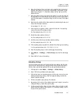
6. Raise the phase setting and check each adjustment by printing test
patterns. Stop when a you produce a test pattern with voids or dark
defects (see Figure 6.1 ). Note this setting; it is the
high end
of the
phase window.
7. Raise the phase setting, and print a test pattern to check the effect of
the adjustment. Continue this process until you produce a test pattern
with no visible defects. Note this setting; it is the
low end
of the phase
window.
8. Determine the middle of the phase window by subtracting the low end
value from the high end value.
For example: 12 - 48 = -36.
9. If the result is a negative number, subtract it from 56. The resulting
value is the size of the phase window.
For the example above: 56 - 36 = 20.
10. Divide the phase window size by 2.
For the example above: 20 ÷ 2 = 10.
11. Add this value to the low-end phase window setting.
For the example above: 48 + 10 = 58.
12. If the resulting value exceeds 55, subtract it from the high-end setting.
For the example above: 48 + 10 = 58; 12 - 10 = 2.
13. Note the resulting value; it is the mid-range phase setting.
14. Select
Mode
→
Settings
→
Printer Setup
and enter the mid-range
value.
15. Press APPLY to save this setting.
Adjusting Voltage
Use the following procedure to determine the print window and the mid-
range value to be used as the voltage setting. This procedure assumes
that you have printed test patterns that reveal print quality problems.
1. In Diagnostics, select
Mode
→
Settings
→
Printer Setup
.
2. Enter 165 for the printhead volts parameter.
3. If the printer does not operate properly at 165 volts, reduce the volts
setting incrementally until you find the highest setting at which the
printer operates properly.
4. Print a test pattern and examine it for defects.
5. Beginning at 165 volts (or the setting determined in step 2), lower the
voltage setting by 5 and check print quality.
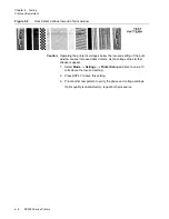
6. Continue lowering the voltage incrementally until you produce a test
pattern with dark defects (see Figure 6.2 ). Note this setting; it is the
low end of the print window
.
Содержание VERSAMARK DP5120
Страница 1: ...Versamark DP5000 Series Printers DP5120 DP5122 and DP5240 Installation Guide ...
Страница 2: ......
Страница 3: ...Versamark DP5000 Series Printers DP5120 DP5240 and DP5122 Installation Guide ...
Страница 8: ......
Страница 12: ...Contents Figures 4 DP5000 Series Printers ...
Страница 14: ...Contents Tables 4 DP5000 Series Printers ...
Страница 32: ...2 16 DP5000 Series Printers Chapter 2 Unpacking Printheads ...
Страница 52: ...3 20 DP5000 Series Printers Chapter 3 Printer Installation Printer Connections ...
Страница 76: ...B 2 DP5000 Series Printers Appendix B Tach and Cue Wiring ...
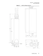
Страница 79: ...Installation Guide C 3 Appendix C Site Requirements Space Requirements Figure C 1 DH5122 printhead dimensions ...
Страница 80: ...C 4 DP5000 Series Printers Appendix C Site Requirements Space Requirements ...
Страница 81: ......

