Installation Guide
B-1
Appendix B. Tach and Cue Wiring
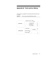
Use Figure B.1 as a guideline for wiring the standard tach encoder and
cue sensor.
Figure B.1
Tach and cue wiring, DP5000 series printers
Tach Encoder
Cue Sensor
INVERTED CUE SIG (GRN)
+5 VDC (RED)
TACH IN (BRN)
TACH IN (BRN)
GND (BLK)
3
7
8
5
9
6
CUE IN (WHITE)
+12 VDC (RED)
GRD (BLACK)
Содержание VERSAMARK DP5120
Страница 1: ...Versamark DP5000 Series Printers DP5120 DP5122 and DP5240 Installation Guide ...
Страница 2: ......
Страница 3: ...Versamark DP5000 Series Printers DP5120 DP5240 and DP5122 Installation Guide ...
Страница 8: ......
Страница 12: ...Contents Figures 4 DP5000 Series Printers ...
Страница 14: ...Contents Tables 4 DP5000 Series Printers ...
Страница 32: ...2 16 DP5000 Series Printers Chapter 2 Unpacking Printheads ...
Страница 52: ...3 20 DP5000 Series Printers Chapter 3 Printer Installation Printer Connections ...
Страница 76: ...B 2 DP5000 Series Printers Appendix B Tach and Cue Wiring ...
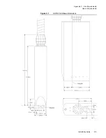
Страница 79: ...Installation Guide C 3 Appendix C Site Requirements Space Requirements Figure C 1 DH5122 printhead dimensions ...
Страница 80: ...C 4 DP5000 Series Printers Appendix C Site Requirements Space Requirements ...
Страница 81: ......

