


Installation Guide
3
Figures
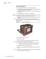
Figure 2.1
Printer on shipping pallet ......................................................... 2 - 2
Figure 2.2
Printing system pallet, shrink wrap removed ........................... 2 - 5
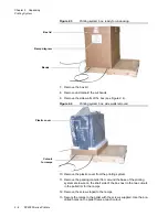
Figure 2.3
Printing system box, ready for unpacking................................ 2 - 6
Figure 2.4
Printing system box, side walls removed................................. 2 - 6
Figure 2.5
DH5120 printhead, capsule inside inner box ......................... 2 - 13
Figure 2.6
DH5240 printhead, capsule inside inner box ......................... 2 - 14
Figure 2.7
DH5122 printhead.................................................................. 2 - 15
Figure 3.1
Printer on stand ....................................................................... 3 - 2
Figure 3.2
Screw locations, printer stand.................................................. 3 - 2
Figure 3.3
Printer positioning limits, height and distance.......................... 3 - 3
Figure 3.4
Ink bottle compartment, DP5122 printer .................................. 3 - 5
Figure 3.5
External 20-liter cubitainer fluid supply .................................... 3 - 7
Figure 3.6
External 55-gallon supply containers....................................... 3 - 8
Figure 3.7
Voltage selector switch cover .................................................. 3 - 8
Figure 3.8
Fuse removal, circuit breaker switch ....................................... 3 - 9
Figure 3.9
Voltage selector switch, DP5120 and DP5240 ........................ 3 - 9
Figure 3.10 Connectors, printer back panel.............................................. 3 - 10
Figure 3.11 Power cord connector, printer back panel ............................. 3 - 11
Figure 3.12 Ethernet connection, printer back panel ................................ 3 - 12
Figure 3.13 RS 232 (serial) connection, printer back panel...................... 3 - 13
Figure 3.14 Parallel data connection, printer ............................................ 3 - 14
Figure 3.15 Control I/O connection, printer back panel ............................ 3 - 15
Figure 3.16 Tach and cue connection....................................................... 3 - 16
Figure 3.17 K4K connection, DP5240....................................................... 3 - 17
Figure 3.18 Connector wiring, relay contact cable.................................... 3 - 19
Figure 3.19 Sort relay cable connection, printer back panel..................... 3 - 19
Figure 4.1
Cabinet, ready for positioning .................................................. 4 - 1
Figure 4.2
Enclosure ready for positioning ............................................... 4 - 2
Figure 4.3
Controller components on system enclosure........................... 4 - 3
Figure 4.4
Hardware and cable kit cables................................................. 4 - 3
Figure 4.5
Power cord connection, printing system .................................. 4 - 5
Figure 4.6
Controller PC connectors, back panel ..................................... 4 - 6
Figure 4.7
Controller data, keyboard and mouse cables .......................... 4 - 7
Figure 4.8
Video connection, controller PC .............................................. 4 - 7
Figure 4.9
PC and monitor power cables.................................................. 4 - 8
Figure 5.1
DH5120 printhead, in shipping container................................. 5 - 2
Figure 5.2
DH5240 printhead, in shipping container................................. 5 - 3
Figure 5.3
DH5122 printhead in shipping container.................................. 5 - 4
Figure 6.1
Missing spots or bands of print ................................................ 6 - 5
Figure 6.2
Dark defect, defines low end of print window .......................... 6 - 7
Figure B.1
Tach and cue wiring, DP5000 series printers .......................... B - 1
Figure C.1
DH5122 printhead dimensions ............................................... C - 3
Содержание VERSAMARK DP5120
Страница 1: ...Versamark DP5000 Series Printers DP5120 DP5122 and DP5240 Installation Guide ...
Страница 2: ......
Страница 3: ...Versamark DP5000 Series Printers DP5120 DP5240 and DP5122 Installation Guide ...
Страница 8: ......
Страница 12: ...Contents Figures 4 DP5000 Series Printers ...
Страница 14: ...Contents Tables 4 DP5000 Series Printers ...
Страница 32: ...2 16 DP5000 Series Printers Chapter 2 Unpacking Printheads ...
Страница 52: ...3 20 DP5000 Series Printers Chapter 3 Printer Installation Printer Connections ...
Страница 76: ...B 2 DP5000 Series Printers Appendix B Tach and Cue Wiring ...
Страница 79: ...Installation Guide C 3 Appendix C Site Requirements Space Requirements Figure C 1 DH5122 printhead dimensions ...
Страница 80: ...C 4 DP5000 Series Printers Appendix C Site Requirements Space Requirements ...
Страница 81: ......


