background image

Vacuum Degasser Unit 

17 


Installation 

Installing the Degasser Unit 

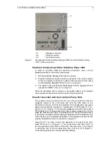
The Smartline Manager 5000 with degasser unit can only be used in 
combination with the Smartline Pump 1000. A special gray connection 
cable (G0649) must be installed on the back side to ensure the 
functionality of the degasser unit. To guarantee the electrical power 
supply of the Smartline Manger 5000 by the Smartline Pump 1000 the 
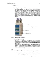
devices must be placed in a tower, where the Smartline Manager 5000 is 
arranged on the Pump 1000 (see Figure 9). As soon as the Smartline 
Pump 1000 is switched on the vacuum pump of the degasser unit will 
operate. 


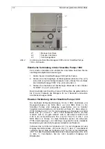
Figure 9 

 Smartline Tower Arrangement  

Connecting the Tubings 

Solvent lines to be degassed are connected to the Vacuum Degasser’s 
front panel ports, as detailed below. Unused ports must be plugged with 
the blind fittings to enable the degasser to operate at its peak level of 
performance. 

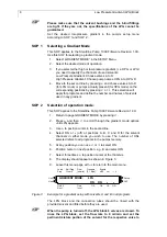
To make a proper tubing connection, please follow the instructions and 
scheme. The Smartline Manager 5000 accessory kit is equipped with pre-
cut PFTE tubings (see also Table 3). A colour identification will help to 
install the compatible tubings. 


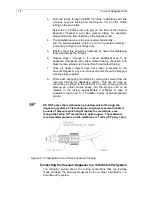
All supplied tubings are pre-cut and should be installed to bring 
about the shortest distance between the connecting ports


1.  Run a blue marked 1 m solvent line of 1/8” O.D. x 1/16” I.D. 

PTFE chromatography tubing from the solvent supply to the 
Vacuum Degasser. 

2.  Install at the one end of the solvent tubing the eluent filter. 

Solvent Tray 


Manager 5000 with Degasser Unit 


Pump 1000 


UV Detector 2500 

Содержание Smartline Manager 5000

Страница 1: ...50 00 00 0 M Ma an nu ua al l H Ha an nd db bu uc ch h V 7602 10 2007 Wissenschaftliche Gerätebau Dr Ing Herbert Knauer GmbH Hegauer Weg 38 D 14163 Berlin Germany Tel 49 0 30 809 727 0 Fax 49 0 30 801 50 10 E Mail info knauer net Internet www knauer net ...

Страница 2: ...nit 11 Spare parts and accessories 12 Technical Data and Specifications 13 Connection 14 Front Panel Connections 14 Front Panel LEDs 14 Rear Panel Connections 15 System Requirements 16 Solvents Mobile Phase 16 Chemical compatibility 16 Space Requirements 16 Electrical Power Requirements 16 Installation 17 Installing the Degasser Unit 17 Connecting the Tubings 17 Connecting the Vacuum Degasser in a...

Страница 3: ...atement 55 Declaration of conformity 56 I N H A L T Hinweise zum Gebrauch des Handbuchs 29 Konventionen in diesem Handbuch 29 Wichtiger Hinweis 29 SOP s in diesem Handbuch 30 Smartline Manager 5000 30 Vielseitigkeit auf kleinstem Raum 30 Niederdruckgradienten NDG Block 31 Allgemeine Beschreibung 31 Installation 31 Elektrische Verbindung mit der Smartline Pumpe 1000 32 Eluenten Verbindung mit der S...

Страница 4: ...ßige Wartung 48 Leckdetektion 48 Fehlersuche 49 Interface Modul 50 Inhalt des Beipacks zum Smartline Manager 5000 Interface Modul 50 Geräteansichten und Anschlüsse 50 Vorderansicht des Gerätes 50 Rückseite des Gerätes 51 Analoge Eingänge AN IN 51 Analoge Ausgänge AN OUT 51 Digitale Eingänge DIG IN 52 Digitale Ausgänge DIG OUT 52 RS232 Schnittstelle 52 Anschließen des Smartline Manager 5000 Interfa...

Страница 5: ...w keys À The triangles symbolize the use of corresponding arrow keys Importend Hint Dear KNAUER customer if you are going to use a Smartline Pump 1000 with low pressure gradient please check whether or not the serial numbers of your Smartline Pump 1000 and your Smartline Manger 5000 fit together If the serial numbers do not fit according the table below please contact KNAUER or your local KNAUER r...

Страница 6: ...he choice The combination of the Smartline Manager 5000 equipped with the LPG module with the Smartline Pump 1000 provides for a quaternary LPG system The maximum flow rate per channel depending on the pump head can reach up to 50 ml min The valve block made of highly resistant PEEK is controlled by the Smartline Pump 1000 and delivers gradient mixtures of the highest precision over the entire flo...

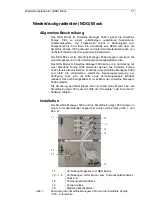
Страница 7: ...on with a Smartline Pump 1000 The Smartline Pump 1000 controls all electrical functions on the Smartline Manager 5000 and provides the required electrical power supply This is realized with a connection cable G0649 The connection cable is included in the accessories for the Smartline Manager 5000 The control of the LPG block can be obtained in the stand alone mode over the Smartline Pump 1000 or w...

Страница 8: ... shut off Eluent Connection with the Smartline Pump 1000 The required tube connections for the four LPG connections from the degasser output to the LPG block and from the LPG block to the Smartline Pump are cut to fit and included in the accessories see spare parts and accessories on page 12 Included are 4 PTFE tubes 0 11 m see Pos 1 1 in Figure 1 to connect the degasser to the LPG block and 4 PTF...

Страница 9: ...ode This SOP applies to the Smartline Pump 1000 Firmware Revision 1 0X 1 Return to page GRADIENT MODE by pressing 2 Press and then to scroll through the gradient mode options until LPG appears 3 Use to position cursor in the second line 4 Select ON or off at positions A B C and D for the solvent channels in either mode you wish to use The number of ONs selected refers to all programs in the pumps ...

Страница 10: ...or all valves that will be used During operation the yellow LEDs A to D in front of the Smartline Manager display the respective valve openings The accessory kit of the Smartline Manager 5000 includes a static mixing chamber It will be fixed at the front site of the pump see pos 1 7 in Figure 1 on page 6 The mixing chamber enables an optimum mixing of eluents in the range of 0 5 to 2 0 ml min Tech...

Страница 11: ...e pump head with a small bleed of air to remove any solvent vapors which may enter the vacuum pump from the vacuum chamber This air bleed eliminates the need for any solenoid valves within the system This patented design results in zero vacuum hysteresis Previous designs allowed the vacuum chamber pressure to fluctuate with the pump cycling on and then off in response to the vacuum level Principle...

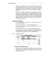
Страница 12: ...rt term Shutdown procedures General Description The Smartline Degasser analytical version is available for flow rates up to 10 ml min per channel Smartline Manager 5000 4 channel analytical degasser unit The semipreparative version of the Smartline Degasser can be used for flow rates up to 50 ml min Smartline Manager 5000 2 channel semipreparative degasser unit The degasser unit is configured in t...

Страница 13: ...g 1 m with eluent filter yellow channel B G1440 3 1 PTFE tubing 1 m with eluent filter blue channel A G1440 4 1 PTFE tubings 0 11 m from degasser to LPG unit P9170 A0732 4 PTFE tubing 0 14 m from semiprep degasser to LPG unit P9172 A0732 1 PTFE tubing 0 44 m for HPG unit P9172 A0732 1 PTFE tubing 0 27 m from LPG channel D to pump red G0766 1 PTFE tubing 0 28 m from LPG channel C to pump black G076...

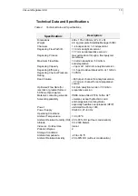
Страница 14: ...l Pressure Rating 70 PSIG Dead Volume 480 µl per channel for analytical version 7 7 ml per channel for semipreparative version Optimized Flow Rate for isocratic or gradient formed 50 50 methanol water 3 ml min analytical version 30 ml min preparative version Materials contacting solvents PEEK Glass filled PTFE Teflon AF Solvent Applicability universal except hydrochloric acid and halogenated carbo...

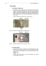
Страница 15: ... connection of both degasser units with LPG unit is shown Plugs are provided to seal the ports of unused channels A B C D Flow Degasser LPG Unit Figure 5 Degasser Tubing Connection analytical version A B Degasser LPG Unit Flow Figure 6 Degasser Tubing Connection semiprep Version Front Panel LEDs The green power LED in the upper left part of the Manager front door indicates the general state of rea...

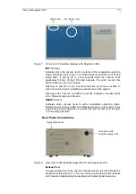
Страница 16: ...possible leak in the system Flashing on for 1 second and off for 2 seconds indicates a vacuum signal error Please contact your Service READY Green Indicates when vacuum level is within acceptable operating range Normally it will come on after the initial pump down and remain on as long as the Vacuum Degasser is powered up and vacuum level is below 100 mm of Hg absolute Rear Panel Connections Conne...

Страница 17: ...rt to all solvents normally used in HPLC However Teflon AF is soluble in perfluorinated solvents such as Fluorinert FC 75 and FC 40 and Fomblin perfluoro polyether solvents from Ausimont In addition Freon solvents will adversely affect Teflon AF Use of such solvents in the Vacuum Degasser will result in the dissolution and hence destruction of the membrane Use proper care when handling flammable s...

Страница 18: ...ings Solvent lines to be degassed are connected to the Vacuum Degasser s front panel ports as detailed below Unused ports must be plugged with the blind fittings to enable the degasser to operate at its peak level of performance To make a proper tubing connection please follow the instructions and scheme The Smartline Manager 5000 accessory kit is equipped with pre cut PFTE tubings see also Table ...

Страница 19: ...e Vacuum Degasser any and all unused ports should be plugged Use the plugs supplied 8 Prime each degassing membrane by pulling the solvent from the reservoir through the degassing system This can be done by connecting a syringe to the tubing or LC pump priming port and drawing air and or mobile phase into the syringe until no air remains in the tubing approximately 2 milliliters in case of analyti...

Страница 20: ...Vacuum Degasser Unit 19 analytical Degasser Unit LPG Unit Figure 11 Smartline LPG System Tubing Connections Smartline Manager 5000 Smartline Pump 1000 Smartline Detector 2500 A B C D A B C D ...

Страница 21: ...g the speed of the vacuum pump as needed depending on the degassing load in the system The pump is designed to run continuously for at least 5 years and is equipped with integral in pump venting eliminating the need for stop start running U S Patent 6 248 157 The vacuum level and pump speed is constantly monitored by the microprocessor for changes in operating conditions which might be attributed ...

Страница 22: ... it is a general rule that only the organic portion of the mobile phase needs to be passed through a second degassing channel to ensure outgassing does not occur This is due to the ability of all organic solvents e g methanol to hold at least 10 times more dissolved atmosphere than water can To more thoroughly degas a mobile phase connect the outlet of the organic channel to the inlet a second cha...

Страница 23: ...ently at an optimal level To maintain the Vacuum Degasser in the best condition the following measures are recommended 1 Adhere to standard laboratory cleanliness practices Use only high purity solvents preferably HPLC grade for mobile phases Water should be bottled HPLC grade or filtered and deionized tap water Filter all solvents to prevent particulate contamination and tubing blockages 2 Use on...

Страница 24: ...nded period of time as heard by the pitch of the stepper motor it could indicate a potential fault condition Orange INIT LED is flashing approximately 1 second off 1 second on Vacuum pump is not running Possible system leak Contact your Service Representative Orange INIT LED is flashing approximately 2 seconds off 1 second on Vacuum pump is not running Possible sensor or control board fault Contac...

Страница 25: ...ns that are supported by the control software can be found in the software manual Configuring and programming the Smartline Manager 5000 Interface Module s control software is described in the respective manual of the software Contents of the accessory kit for the Smartline Manager 5000 Interface Module 4 x WAGO strips 9 pin 1 x WAGO lifting latch 1 x Zero modem connection cable RS 232 socket sock...

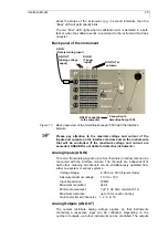
Страница 26: ...ule and on the instruments that will be controlled If the maximum voltage and current are exceeded KNAUER is not liable for defective instruments Analog Inputs AN IN To record from analog signals up to four channels or instruments can be connected with the interface module The channels are independent of each other meaning all channels can be simultaneously operated from either one system or vario...

Страница 27: ...ble trough SPDT They can be selected as NO normally open connection 2 3 see the back panel view or NC normally closed connection 1 2 see the back panel view Pulse or continuous signals can be programmed The length of a pulse contains approximately 1s the length of the continuous signal can be freely programmed Output type selectable NO or NC Maximum switching voltage maximum 175 V DC Maximum switc...

Страница 28: ...ce module and on the instruments that will be controlled If the maximum voltage and current are exceeded KNAUER is not liable for defective instruments The WAGO plug strips and cable that are required for connection are included in the Smartline Manager 5000 Interface Module s accessory kit The analog input and output of one channel can not be used simultaneously Digital Connections The digital in...

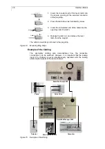
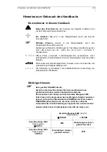
Страница 29: ...from the plug 2 The cable is now firmly anchored in the plug strip Figure 14 Mounting Plug Strips Example of the Cabling The exemplary cabling plan demonstrates how the respective connections can be switched However it is important that the analog input of a channel is never simultaneously operated with the analog and or digital outputs of the same channel Smartline Pump 1000 Pump Valve Drive Dete...

Страница 30: ... bedeuten dass der Anwender die entsprechende Pfeiltaste betätigen soll À Die Pfeilspitzen symbolisieren die selbstdefinierende Verwendung der entsprechenden Pfeiltasten Wichtiger Hinweis Sehr geehrter KNAUER Kunde Wenn Sie Ihre Smartline Pump 1000 mit einem Niederdruck gradienten betreiben wollen überprüfen Sie bitte die Seriennummern der Pumpe und des Smartline Managers 5000 Falls diese nicht en...

Страница 31: ...er mit einem Niederdruckgradienten Modul NDG einem Degasser Modul und einem Interface Modul ausgestattet werden Sie haben die Wahl Das NDG Modul im Smartline Manager 5000 ergänzt die Smartline Pump 1000 zu einem vollständigen quaternären Niederdruck Gradientensystem Der Flussbereich reicht in Abhängigkeit vom Pumpenkopf bis 50 ml min Ein Ventilblock aus widerstandsfähigem PEEK wird über die Smartl...

Страница 32: ...en Die Smartline Pumpe 1000 steuert alle elektrischen Funktionen des Smartline Managers 5000 und stellt die erforderliche elektrische Spannungsversorgung zur Verfügung Dies wird mit Hilfe eines Verbindungskabels G0649 realisiert Das Verbindungskabel ist im Zubehör des Smartline Managers 5000 enthalten Die Steuerung des NDG Blocks kann im Stand alone Modus über die Smartline Pumpe 1000 oder mit Hil...

Страница 33: ...ten Verbindung mit der Smartline Pumpe 1000 Die benötigten Schlauchverbindungen für die 4 NDG Anschlüsse vom Degasser Ausgang zum NDG Block und vom NDG Block zu der Smartline Pumpe sind maßgenau zugeschnitten und im Zubehör beigefügt siehe Ersatzteile und Zubehör auf Seite 37 Dazu zählen 4 PTFE Schläuche 0 11 m für den Anschluss vom Degasser zum NDG Block Pos 1 1 in Abb 1 und 4 PTFE Schläuche 0 27...

Страница 34: ...en zusammen Diese Auswahl wird auf die Programme angewendet und bestimmt die Anzahl und die Namen der in einem beliebigen Gradienten eingesetzten Lösungsmittel SOP 2 Auswahl der Betriebsart Diese SOP gilt für die Smartline Pumpe 1000 Firmware Version 1 0X 1 Gehen Sie mit der Taste zur Seite GRADIENT MODE 2 Drücken Sie die Taste und blättern dann mit der Taste durch die GRADIENT MODE Optionen bis L...

Страница 35: ...e des Druckaufnehmers der Smartline Pumpe 1000 siehe Pos 1 7 in Abb 1 eine Verbindung herstellen Saugen Sie solange bis keine Luftblasen mehr in der Lösung erscheinen Wiederholen Sie diesen Vorgang für alle zu verwendenden Ventile Während des Betriebes zeigen die gelben LEDs A bis D an der Frontseite des Smartline Managers 5000 das jeweilige Öffnen der Ventile an Im Beipack des Smartline Manager 5...

Страница 36: ... Mikropumpe erhält ein konstantes Vakuum von 50 mm Hg 67 mbar aufrecht damit die gelösten Gase durch die mikroporöse Membran dem Eluenten entzogen werden können siehe Abb 4 Dieser dynamische Entgasungsprozess wird durch den Konzentrationsgradienten zwischen beiden Seiten der Membran realisiert Die Vakuumpumpe kann bei diesem Prozess ein konstantes Vakuum durch die Anpassung der Pumpengeschwindigke...

Страница 37: ... Vakuumpumpe und dem konstanten Absaugen der Gasphase dazu kommen dass Auskristallisierungsprozesse in der Degasserkammer stattfinden können Das Auskristallisieren kann zu einer Blockierung innerhalb der Degasserkammern führen und ist durch eine geeignete Vorgehensweise zu vermeiden siehe Seite 47 Abschaltung Allgemeine Beschreibung Der Smartline Degasser ist in der analytischen Version für Flussr...

Страница 38: ...er rot Kanal D G1440 1 PTFE Schläuche 1 m mit Eluentenfilter schwarz Kanal C G1440 2 4 PTFE Schläuche 1 m mit Eluentenfilter gelb Kanal B G1440 3 PTFE Schläuche 1 m mit Eluentenfilter blau Kanal A G1440 4 PTFE Schläuche 0 11 m vom Degasser zur NDG Einheit P9170 A0732 4 PTFE Schlauch 0 14 m vom präp Degasser zur NDG Einheit P9171 A0732 1 PTFE Schlauch 0 44 m für HPG Pumpenanschluss P9172 A0732 1 PT...

Страница 39: ...ntgasungsleistung 0 5 ppm restlich gelöster O2 bei 1 ml min Vakuum 67 mbar Totvolumen 480 µl pro Kanal für die analytische Version 7 7 ml pro Kanal für die semipräparative Version optimale Flussrate isokratisch oder Gradient 50 50 Methanol Wasser 3 ml min analytische Version 30 ml min semipräparative Version Kontaktmaterialien PEEK PTFE Teflon AF Lösungsmittel beständigkeit universell ausgenommen ...

Страница 40: ... Kammern vertikal von unten nach oben angeschlossen siehe Abb 5 und Abb 6 Wird eine Degasserkammer nicht benutzt so sollten die mitgelieferten Verschraubungen den Ein und Ausgang der entsprechenden Kammer verschließen A B C D Fluss Degasser NDG Block Abb 5 Installation der Schlauchverbindungen analytische Version A B Degasser NDG Block Fluss Abb 6 Installation der Schlauchverbindungen semipräp Ver...

Страница 41: ...nge LED Dies dauert im Normalfall weniger als 30 Sekunden Wird ein Fehler diagnostiziert so kann die LED in zwei verschiedenen Arten leuchten Die LED geht in 1 s Intervallen ständig an und aus Dies zeigt an dass die Vakuumpumpe das definierte Vakuum von 67 mbar nicht erreicht Ein Leck im System kann die Ursache sein Die LED geht für 1 s an und für 2 s aus Dies zeigt einen Fehler des Vakuum Signals...

Страница 42: ...e Phase Da die Teflon AF Membran eine sehr hohe chemische Beständigkeit hat und als inert bezeichnet wird können alle bekannten HPLC Lösungsmittel inklusive THF und Methylenchlorid verwendet werden Wird mit Pufferlösungen gearbeitet so sind alle Leitungen nach Beendigung der Nutzung mit Wasser zu spülen Lassen Sie den Degasser nicht über einen längeren Zeitraum mit Wasser bzw gepufferten wässrigen...

Страница 43: ... Manager 5000 wird im Turm zwischen der Lösungsmittelwanne und der Smartline Pumpe 1000 angeordnet Der Smartline Manager 5000 benötigt ein Volumen von 226 x 135 x 390 mm L x H x T Da alle Schläuche und Verschraubungen durch die Vordertür verdeckt werden ist kein zusätzlicher Raum zur Installation nötig Stromversorgung Der Degasser im Smartline Manager 5000 hat keine eigene Stromversorgung sondern ...

Страница 44: ...sen 1 Entfernen Sie die Blindverschraubungen von den Ein und Ausgängen der Degasserkammern die benutzt werden sollen Bewahren Sie diese zum evtl späteren Verschließen der Degasserkanäle sorgfältig auf 2 Führen Sie die 1 m lange blau markierte PTFE Schlauchverbindung 1 8 A D x 1 16 I D vom Lösungsmittelvorratsbehälter durch die vorgesehenen Bohrungen der Lösungmittelwanne zum Degassereingang 3 Inst...

Страница 45: ...rs sollten mit den dafür vorgesehenen Verschraubungen verschlossen werden 8 Spülen Sie die Degasserkammer mit dem dafür vorgesehenen Lösungsmittel indem Sie am Degasserausgang eine Verbindung zu einer Spritze oder direkt zur Pumpe herstellen Saugen Sie solange das Lösungsmittel durch die Degasserkammer bis keine Luftblasen mehr erscheinen In der Regel sind für einen Spülvorgang 2 ml Lösungsmittelv...

Страница 46: ... leuchten Sobald das Gerät eingeschaltet ist kontrolliert ein Mikroprozessor das Signal vom Vakuumsensor um zu gewährleisten dass das Vakuum innerhalb des vorgegebenen Bereiches liegt Während der Anfangsphase regelt der Mikroprozessor die Geschwindigkeit der Vakuumpumpe hohe Umdrehungszahlen um schnell den eingestellten Wert für das Vakuum zu erreichen Sobald das Vakuum unter 100 mg Hg fällt wird ...

Страница 47: ...roprozessor überwacht werden können abweichende Bedingungen durch eventuell auftretende Undichtigkeiten sofort diagnostiziert werden Wird eine undichte Stelle durch Verlust des Vakuums diagnostiziert die Pumpe fördert mit mehr als 300 Umdrehungen pro Minute über einen Zeitraum von mehr als 30 Minuten erfolgt eine automatische Abschaltung der Pumpe und die orange INIT LED leuchtet auf Solange der D...

Страница 48: ... die gesundheitsgefährdende Zersetzungs bzw Umlagerungsprodukte bilden können 1 Spülen Sie die Säule entsprechend den Vorgaben des Säulenherstellers Pufferlösungen sollten unbedingt mit Wasser aus dem gesamten HPLC System entfernt werden da es durch Verdampfung zu Kristallisationen kommen kann die den Degasser und das System blockieren stören können Bei Lösungsmitteln welche zur Zersetzung neigen ...

Страница 49: ...artungsarbeiten durchgeführt werden 1 In Anlehnung an die Standardlaborpraxis für sauberes Arbeiten Verwenden Sie nur hochreines Lösungsmittel bevorzugt HPLC Grade als mobile Phase Wasser als Lösungsmittel sollte ebenfalls diesem Standard entsprechen bzw gefiltert und deionisiert sein Filtrieren Sie alle Lösungsmittel um Verstopfungen Blockierungen zu vermeiden 2 Benutzen Sie nur hochreines Gas um...

Страница 50: ...bstand von 1 s auf und die Vakuumpumpe ist aus Möglicherweise ein Systemleck Nehmen Sie Kontakt zum Service auf Orange INIT LED leuchtet alternierend im Abstand von 2 s auf und die Vakuumpumpe ist in Betrieb Möglicherweise eine Störung des Mikroprozessors oder des Überwachungssystems Nehmen Sie Kontakt zum Service auf Gibt es eine Möglichkeit die korrekte Arbeitsfähigkeit des Degasser zu überprüfe...

Страница 51: ...ist zwingend erforderlich Welche Funktionen des Interface Moduls von der Steuersoftware unterstützt werden entnehmen Sie bitte dem Handbuch der Software Die Konfigurierung und Programmierung des Smartline Managers 5000 Interface Moduls in der Steuersoftware sind im Handbuch der entsprechenden Software beschrieben Inhalt des Beipacks zum Smartline Manager 5000 Interface Modul 4 x WAGO Leiste 9 poli...

Страница 52: ...n hervorgerufenen Defekten keine Haftung übernehmen Analoge Eingänge AN IN Gedacht für die Aufnahme von Analogsignalen können bis zu vier Kanäle bzw Geräte mit dem Interface Modul verbunden werden Die Kanäle sind unabhängig voneinander das bedeutet dass alle Kanäle entweder von einem System oder von verschiedenen Systemen gleichzeitig benutzt werden können Voltage Range 2 56 to 2 56 V bipolar mode...

Страница 53: ...ly closed Anschluss 1 2 s Abb 13 zu verwenden Es können Puls oder Dauersignale programmiert werden Die Dauer eines Pulses beträgt ca 1 s die Länge des Dauersignals kann frei programmiert werden Output type wahlweise NO oder NC Max switching voltage max 175 V DC Max switching current max 0 25 A RS232 Schnittstelle Diese Schnittstelle ist eine 9 polige Standard RS232 Schnittstelle auch serielle Schn...

Страница 54: ...Überschreitung kann das Gerät zerstört werden KNAUER kann für diesen Fall nicht haftbar gemacht werden Die zur Verbindung erforderlichen WAGO Steckerleisten und Kabel sind im Beipack zum Smartline Manager 5000 Interface Modul enthalten Analogausgang und eingang eines Kanals können nicht gleich zeitig benutzt werden Digitalverbindungen Die Digitaleingänge können zur Weiterleitung eines von der Inje...

Страница 55: ...entfernen Sie dann das Hebelwerkzeug aus dem Stecker 2 Das Kabel ist jetzt im Anschlussstecker gut verankert Abb 14 WAGO Anschluss Verkabelungsbeispiel Dieser Verkabelungsplan soll beispielhaft zeigen wie die entsprechenden Anschlüsse geschaltet werden können Dabei ist zu beachten dass der Analogeingang eines Kanals niemals gleichzeitig mit den Analog und oder Digitalausgängen desselben Kanals ben...

Страница 56: ...s are borne by the purchaser Gewährleistungsbedingungen Die werksseitige Gewährleistung für den Smartline Manager 5000 beträgt ein Jahr ab Versanddatum Unsachgemäße Bedienung des Gerätes und Folgen einer Fremdeinwirkung sind hiervon ausgenommen Ebenso sind Verschleißteile Dichtungen und Verstopfungsschäden von der Gewährleistung ausgenommen Bitte wenden Sie sich bei Fehlfunktionen Ihres Smartline ...

Страница 57: ... Ordinance 73 23 EWG EN 61010 1 08 2002 Engineering Guidelines 89 392 EWG EMC Ordinance 89 336 EWG EN 6100 3 2 10 2006 EN 61326 1 10 2006 entspricht den folgenden Anforderungen und Produktspezifikationen Niederspannungverordnung 73 23 EWG EN 61010 1 08 2002 Maschinenrichtlinie 89 392 EWG EMV Verordnung 89 336 EWG EN 6100 3 2 10 2006 EN 61326 1 10 2006 The product was tested in a typical configurat...

Отзывы: