14 Vacuum
Degasser
Unit
Connection
Front Panel Connections
Depending upon the model, there are 2 or 4 degassing channels. Pairs of
female ¼-28 connectors are located on the front of the Vacuum Degasser
module on the Smartline Manager 5000. These are the input and output
ports for running up to 4 solvent lines through the Vacuum Degasser.
Each channel has an input port and an output port on the same level. In
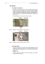
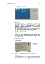
Figure 5 and Figure 6 the connection of both degasser units with LPG
unit is shown.
Plugs are provided to seal the ports of unused channels.
A
B
C
D
Flow
Degasser LPG
Unit
Figure 5
Degasser Tubing Connection,
analytical version
A
B
Degasser LPG
Unit
Fl
ow
Figure 6
Degasser Tubing Connection,
semiprep. Version
Front Panel LEDs
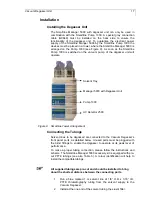
The green power LED in the upper left part of the Manager front door
indicates the general state of readiness. Two additional LEDs are located
on the front door of the Manager unit to show the system status of the
degasser unit.
POWER
(Green)
Indicates when power is applied to the Vacuum Degasser unit (realised
by the Smartline Pump 1000).

