18 Vacuum
Degasser
Unit
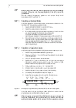
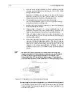
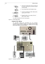
3. Push the tubing through a PEEK 1/8” male ¼-28 fitting and slide
a ferrule over the tubing end (see Figure 10). Cut the Teflon
tubing so the end is flat.
Screw the ¼-28 fitting into one port on the front of the Vacuum
Degasser (channel A with blue marked tubing, for example).
Please follow the flow direction on the Degasser unit.
4. The analytical version is to be connected horizontally
→
and the semipreparative version is to be connected vertically
↑
(comparing to Figure 5 and Figure 6).
5. Plastic connectors should be tightened by hand. Overtightening
them will damage the threads.
6. Repeat steps 1 through 3 to connect additional lines to be
degassed (channel B with yellow marked tubing, channel C with
black marked tubing and channel D with red marked tubing.
7. Once all desired solvent lines have been connected to the
Vacuum Degasser, any and all unused ports should be plugged.
Use the plugs supplied.
8. Prime each degassing membrane by pulling the solvent from the
reservoir through the degassing system. This can be done by
connecting a syringe to the tubing or LC pump priming port and
drawing air and/or mobile phase into the syringe until no air
remains in the tubing, approximately 2 milliliters in case of
analytical version and 8 – 10 milliliter in case of semipreparative
version.
DO NOT prime the membranes by pushing solvent through the
degassing systems. This technique can generate several hundred
pounds of pressure which might rupture the membrane, even
though the Teflon AF
®
membrane is quite rugged. The maximum
recommended pressure on the membrane is 1 mPa (100 psig, 7 bar).
Figure 10 Configuration of ¼-28 Nut, Ferrule and Tubing
Connecting the Vacuum Degasser in a Smartline LPG System
The following picture shows the tubing connections that are typically
made between the Vacuum Degasser Unit and other instruments in a
Smartline LPG system.

