background image

Setup Menu: DN9340E 


28 


7.2.2 

Using a DN9340E for master control 

Comms channels 1 to 32 are available, enabling a mater/slave network with one DN9340E unit acting 

as the master and up to 31 DN9340E and/or DN9344E slave units. 


To select a master remote communications channel 


Press 

HOME (SETUP)

 for more than one second to access the 

Set Up menu; you will be taken immediately to the Comms 

page. 


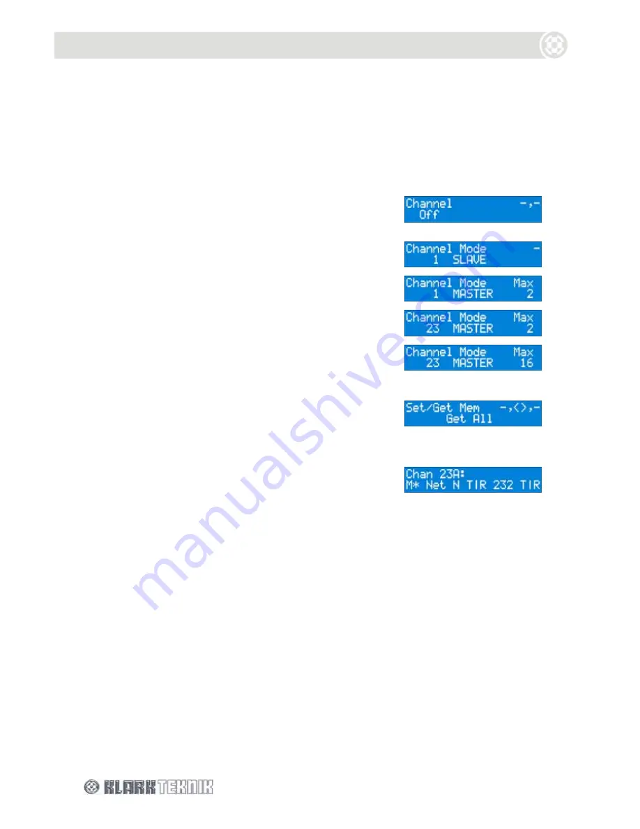
Turn the left control knob clockwise to access the 

communications channels (SLAVE Mode). 


Turn the centre control knob clockwise to display 

communications channels in MASTER Mode. 


Turn the left control knob to select required master channel, 
for example, channel 23. 


Turn the right control knob to select the maximum number 

of inputs in the network, for example, 16.  Inputs are always 

in pairs (two inputs per channel) and you can have a 

maximum of 64. 


Press 

HOME (SETUP)

.  You have the option to upload the 

memory from the networked units (“Get All”) or download 

the memory from this unit to the other networked units 
(“Set All”).  To access the “Set All” option, turn centre 

control knob anti-clockwise. 


Press 

HOME (SETUP)

.  The unit will search for the other 

networked units and then display the following: 


The front panel controls, except the 

HOME (SETUP)

 button, are locked out to facilitate remote operation.  

The display indicates that the unit is the master and is controlling the network. 


To select a slave communications channel 


To set the unit as a slave and select the communications channel, follow the procedure in “To select a 
slave remote communications channel” on page 27. 


To remove the unit from the network 

Press and hold the 

HOME (SET UP)

 button to reopen the Comms page. 

Turn the centre control knob anti-clockwise to select Mode as “SLAVE”. 

Turn the left control knob anti-clockwise until Channel is set to “Off”. 

Press 

HOME (SETUP)

 to confirm your selection. 

Содержание HELIX DN9340E

Страница 1: ...741515 Fax 44 1562 745371 Email info uk telex com Website www klarkteknik com DN9340E DN9344E HELIX V4 00 Operator Manual DOC02 DN9340E 44E Issue A March 2006 Telex Communications UK Limited In line...

Страница 2: ......

Страница 3: ...two blades and a third grounding prong The wide blade or the third prong are provided for your safety If the provided plug does not fit into your outlet consult an electrician for replacement of the...

Страница 4: ......

Страница 5: ...by 92 31 EEC 93 68 EEC 73 23 EEC Low Voltage Directive amended by 93 68 EEC Generic Standard Using EN50130 Limits and Methods EN50081 1 Class B Conducted Emissions EN50130 Class B Radiated Emissions...

Страница 6: ......

Страница 7: ...1 2 DN9344E Front Panel 4 2 INTRODUCING THE DN9340E DN9344E 5 3 FRONT PANEL DN9340E 7 3 1 EQ Access and Displays 7 3 2 Bypass Channel Select Soft Keys and Alphanumeric Display 8 3 3 Touch Strip Store...

Страница 8: ...ddress Page 11 33 7 11 2 Ethernet Subnet Mask Setup Page 12 35 8 STORING AND RECALLING SETTINGS DN9340E 36 9 DN9340E AND DN9344E MASTER SLAVE REMOTE CONTROL 37 9 1 Connections 37 9 2 Addresses 37 9 3...

Страница 9: ...DN9344E 50 15 1 General 50 15 2 Remote Comms channels Page 1 50 15 3 Password Page Page 2 53 15 4 Analogue Digital Input Select Pages 3 and 4 53 15 5 Digital Output Clock Select Pages 5 and 6 54 15 6...

Страница 10: ......

Страница 11: ...em Installation Considerations Location Do not install this unit in a location subjected to excessive heat dust or mechanical vibration Allow for adequate ventilation around the unit making sure the u...

Страница 12: ......

Страница 13: ...his bypasses the complete unit for the selected channel both channels if linked When a particular EQ type is selected by the buttons above the bypass switch the bypass operates on that type of EQ only...

Страница 14: ...nently marking the unit Remove chinagraph markings by wiping with a soft cloth Do not use solvents as these may damage the surface 5 UP and DOWN buttons for sections 1 and 2 Selects various set up men...

Страница 15: ...r and an equaliser This approach has the disadvantage that while it is usually fairly easy to determine the level at which the dynamic EQ will start to operate it is much harder to visualise the likel...

Страница 16: ...cludes two types of memory location to provide maximum flexibility in a range of applications There are 32 user memories in battery backed up SRAM and 32 preset memories in non volatile FLASH memory R...

Страница 17: ...not just an indication of the bypass state For example if all the faders on the graphic EQ are flat then the LED will not illuminate If the graphic is not bypassed and then a fader is moved away from...

Страница 18: ...indicators will be illuminated and the button will be inoperative 3 Soft keys Soft keys for selecting options and secondary functions These keys illuminate to indicate whether they are active in a pa...

Страница 19: ...uttons Used to store complete unit settings to one of the 32 user memory locations and then to recall them In addition to user memories settings may be recalled from 32 preset memories that can only b...

Страница 20: ...clip indication This meter indicates the input level immediately after the input gain trim 3 Metering Dynamic EQ metering Four meters are used for monitoring the four dynamic EQ filters 4 Output Mete...

Страница 21: ...BU signals Note that when digital input is selected input B is inactive AES EBU is 110 Ohms Sample rate converters SRCs support incoming signals at sampling frequencies from 32kHz to 96kHz 12 5 while...

Страница 22: ...Signal Flow DN9340E 12 5 SIGNAL FLOW DN9340E...

Страница 23: ...delay may be adjusted in coarse increments of 2 08ms one sample at 48kHz sample rate using the left encoder or in fine increments of 0 02 ms with the centre encoder It is displayed in time units by d...

Страница 24: ...Operation DN9340E 14 6 1 3 Touchstrip Operation on the Home Page In the home page the touchstrip is inoperative...

Страница 25: ...so on pressing this allows an individual fader or a selected block of faders to be switched in and out of circuit Faders are shown as when switched out or if selected at the line Default page shows f...

Страница 26: ...isation based on an audio spectrum from a DN6000 Note that the DN9340E auto equalises on the basis of a captured DN6000 snapshot it does not auto equalise in real time The Helix unit generates a recip...

Страница 27: ...0 5dB increments Pressing the strip continuously in the same place will result in the fader ramping up or down over its full range As an aid to resetting faders to exactly 0dB this ramping motion wil...

Страница 28: ...lay After the last page the next press returns to the first page and so on adds a new PEQ section There are 12 PEQ sections available to each channel each of which can be used across the whole frequen...

Страница 29: ...currently active section of EQ as an alternative to using the encoder knobs If you are not currently using the Freq Level menu the unit automatically switches to it when you press the touchstrip Press...

Страница 30: ...ched in and out of circuit Default page displays frequency and Q slope for this section Each of the sections can be used over the whole frequency range from 20Hz to 20kHz and has fully parametric cont...

Страница 31: ...p operation with Dynamic equalisation On the Dynamic EQ page the touchstrip can be used to select the currently active section of EQ If you are not currently using the Freq Level menu the unit automat...

Страница 32: ...king Hi shelf and Lo shelf Turn the right encoder to confirm the selection and create the filter There are four filters available to each channel each of which can be used across the whole frequency r...

Страница 33: ...eft encoder to select the type of filter required The available options are Notch Low pass normal and peaking High pass normal and peaking Hi shelf and Lo shelf Turn the right encoder to confirm the s...

Страница 34: ...ing in a clipped signal but the level is then reduced by a subsequent EQ section the clip LED will still illuminate to indicate the internal clip condition despite the apparently safe output level In...

Страница 35: ...at is required C To ensure that each type of EQ is zeroed out and can be introduced seamlessly into circuit follow this sequence 1 Press HOME SETUP then select the soft key labelled Delay Gain Set del...

Страница 36: ...4 Password Page for preset protection Page 5 LCD Display settings Page 6 Unit naming Page 7 Memory naming Page 8 Delay units of measurement Page 9 Power up logo Page 10 Ethernet settings for remote co...

Страница 37: ...cation you will need to set up the unit s IP address and Subnet mask before selecting the comms channel see Section 7 11 for further details To select a slave remote communications channel 1 Press HOM...

Страница 38: ...ave a maximum of 64 6 Press HOME SETUP You have the option to upload the memory from the networked units Get All or download the memory from this unit to the other networked units Set All To access th...

Страница 39: ...symbols Important Preliminary and subsequent blank spaces are recorded as part of the eight character password Therefore if you use a short password the characters must be re entered in exactly the s...

Страница 40: ...put bypassing sample rate converter input source either 44 1 kHz or 48 kHz to eliminate converter latency Input digital clock is synchronised to clock derived from digital audio input Note clock refer...

Страница 41: ...clock source Note To select DigIn AB the unit s input select must be set to be digital and running in DLck AB mode see Section 7 4 7 6 Presets lock Page 5 This allows the presets to be password prote...

Страница 42: ...clear existing characters enter a blank space which can be found after the letter Z 2 Press HOME SETUP to apply the new name All names are stored with System memory settings The Store function will as...

Страница 43: ...ct unit to PC connections DHCP Dynamic Host Configuration Protocol the IP Address is provided automatically by the DHCP server in your network This mode is recommended for large networks as it avoids...

Страница 44: ...3 Press HOME SETUP to confirm the mode change If you now step back through the Set Up menus and check the IP Address again you will see the address assigned by your DHCP server In this mode the IP Add...

Страница 45: ...t will scan the Network to obtain the Subnet Mask 3 Turn the left control knob to highlight the area of the Subnet Mask you wish to change 4 Now turn the centre control knob to select a number from 0...

Страница 46: ...e settings 1 Press STORE 2 Turn left encoder knob to select the destination U01 to U32 for example U02 3 Press STORE again to confirm or HOME SETUP to abort The far left character of the store name fl...

Страница 47: ...t any time two DN9340Es can be replaced by a single DN9344E or vice versa without any need to change the addressing of the system 9 3 Data model Each Helix unit has a working memory which is the curre...

Страница 48: ...to show that it is active 2 Turn left encoder to select the channel number for the master unit Turn the centre encoder to select MASTER mode Turn the right encoder to select the maximum number of audi...

Страница 49: ...lave is next selected for use 9 6 System naming To ensure clarity of operation each slave can be assigned a meaningful name in addition to its channel name 1A 3B etc To set up the names 1 First select...

Страница 50: ...of Midas Heritage and Legend consoles The console RS 232 port is connected to the RS 232 connector D9 on the rear of the master DN9340E unit using a straight wired cable no crossovers Once the channel...

Страница 51: ...ring the event set up as the engineer can move around freely with a laptop and adjust the equalisation while listening to the end effect at any place in the venue Serial option The optional RS 232 ser...

Страница 52: ...typical example of the HELIX DN9340 DN9344E units connected in a daisy chain configuration 10 2 2 Connecting the HELIX DN9340E DN9344E units to an Ethernet switch or hub The diagram below shows each...

Страница 53: ...ocket of the laptop PC The other end is either connected to an Ethernet socket on one of the HELIX DN9340E DN9344E units daisy chain or an Ethernet switch or hub depending on system configuration Note...

Страница 54: ...guring the Elgar Library Manager and HELIX DN9340E RCS add in software please refer to the relevant documentation Note that once remote communications are established the DN9340E display updates to sh...

Страница 55: ...connect set up and configure your system for serial operation 1 Connect the HELIX DN9340E DN9344E units in a daisy chain configuration see Section 10 2 1 2 Power up the HELIX DN9340E DN9344E units an...

Страница 56: ...icates the level immediately after the input gain trim 3 Dynamic EQ Metering for sections 1 and 2 Four separate meters are provided to allow continuous monitoring of all dynamic EQ sections 4 Output M...

Страница 57: ...h markings by wiping with a soft cloth Do not use solvents as these may damage the surface 4 UP and DOWN buttons for sections 1 and 2 Used to select various set up menu options including the communica...

Страница 58: ...4 Analogue Outputs 1A 1B 2A and 2B Electronically balanced XLR audio output plugs Pinouts Pin 1 Screen Pin 2 Hot Pin 3 Return 5 Digital Outputs 1 and 2 Digital AES EBU output for channels 1A 1B and 2A...

Страница 59: ...Signal Flow DN9344 49 13 SIGNAL FLOW DN9344E...

Страница 60: ...e control operation Pages 7 8 and 9 These options are programmed in the Set Up menu and are described below in menu order To access the Set Up menu pages At the Home page press and hold the SET UP but...

Страница 61: ...ns on the right hand half of the unit to select its own independent communications channel The reason for having two separate channel numbers within one unit is that the DN9344E is seen by the system...

Страница 62: ...it Memory recalls are now performed by an external switch or relay that momentarily connects pin 9 of the RELAY connector to one of the other pins Function assignments are as follows Pin 1 recall Pres...

Страница 63: ...the UP button in the right hand section 15 4 Analogue Digital Input Select Pages 3 and 4 The next two pages set the input source and clock reference for input channels 1A and 1B and 2A and 2B on a pa...

Страница 64: ...UP and DOWN buttons on the right hand half of the unit Section 2 to change to a new option 4 Press SETUP to confirm unit will display password menu 5 Press SETUP to exit Note The available options fo...

Страница 65: ...ntly stored IP Address for the DN9344E unit If Auto IP or DCHP have been selected The display is read only and cannot be modified by the user If Manual mode has been selected 1 Use the UP and DOWN but...

Страница 66: ...te between each of the four display fields 2 Now use the UP and DOWN buttons on the right hand half of the unit Section 2 to set the value between 0 255 3 Press SETUP to confirm unit will display pass...

Страница 67: ...on and uses the signal level to directly control parametric equalisers This purely EQ based solution allows simple controls that directly relate to the signal levels As a result it is very easy to set...

Страница 68: ...consider Figure 2 which shows the Helix applying a boost at low signal levels which is automatically wound out at high level In this example low threshold is 20dBu low level is 12dB high threshold is...

Страница 69: ...ol over the maximum amount of boost that will be applied and the level at which this will occur Note the shape of the curve for 5dBu which has expected values outside the filter range and at the centr...

Страница 70: ...y 800Hz and the upper one is at approximately 1 25kHz Therefore this filter has a Q of In a typical parametric equaliser and in the case of the Helix system the graphic and dynamic sections too we hav...

Страница 71: ...points does not change at all as the gain is adjusted The really important thing to notice about this is that the resulting frequency response is NOT symmetrical in cut and boost This is because of th...

Страница 72: ...onses that are symmetrical with the boost ones In other words the bandwidth in cut is defined not according to our usual definition of Q see constant Q above but as the point were the signal is cut by...

Страница 73: ...that the unit is synchronised to the incoming data stream For large digital transmission systems using AES EBU interfaces such as those encountered in broadcast and studio installations a clock signa...

Страница 74: ...24 bit or 16 bit SRC Input at these sample rates Word Clock Input One Type BNC Impedance 75 Analogue Outputs Two Type Electronically balanced pin 2 hot Maximum Level 21dBu into 2k Digital Outputs One...

Страница 75: ...12 Bands max Range 12dB Responses Proportional Constant Reciprocal Graphic EQ 31 Bands On ISO standard frequencies Range 12dB Responses Proportional Constant Reciprocal DN27 DN360 Power Requirements V...

Страница 76: ...le Rate 44 1kHz 48kHz Word Length 24 bit Performance Frequency response 0 5dB with all filters and EQ flat relative to frequency response at 1kHz 20Hz to 20kHz Distortion THD N 4dBu 0 01 20Hz to 20 kH...

Страница 77: ...0W Terminations Audio inputs outputs 3 pin XLR Ethernet inputs outputs Ethercon RS 232 8 pin Mini DIN socket front Relay Socket 9 pin D type rear Power 3 pin IEC Dimensions and Weight Width 483 mm 19...

Страница 78: ...is incorrectly placed Replace only with the same or equivalent type recommended by the manufacturer Discard used batteries according to the manufacturer s instruction Advarsel Lithiumbatteri Ekxplosio...

Отзывы: