


10 english
• Wood which is not correctly glued can explode when be-
ing processed due to centrifugal force.
• Trim work piece to a rectangular shape, center and cor-
rectly secure before processing. Unbalanced work pieces
can be hazardous.
• Injuries can occur when feeding work pieces if tool sup-
ports are not correctly adjusted or if turning tools are
blunt. Sharp turning tools which are free of defects are
necessary for professional turning.
• Long hair and loose clothing can be hazardous when
the work piece is rotating. Wear personal protective gear
such as a hair net and tight fitting work clothes.
• Saw dust and wood chips can be hazardous. Wear pe-
sonal protective gear such as safety goggles and a dust
mask.
• The use of incorrect or damaged mains cables can lead
to injuries caused by electricity.
• Even when all safety measures are taken, some re-
maining hazards which are not yet evident may still be
present.
• Remaining hazards can be minimized by following the
instructions in „Safety Precautions“, „Proper Use“ and
in the entire operating manual.
Start-up
Observe the safety notes in the operating instructions before
operating the machine.
Remove the tensioning spindle or the chuck from the spindle
in addition to any step-up tools before first operating the ma-
chine!
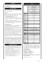
Speed adjustment
The speed can only be adjusted once the machine has
been unplugged.
The correct number of revolutions is visible on the speed
diagram located on the headstock. The speed diagram is
intended for medium-hard dry woods.
The appropriate speed is based on various factors such
as:
• type and compostion of woods
• seasoned, dry woods
• diameter and length of workpieces
• squared or unbalanced woods
• width of pre-worked, balanced workpieces
• wood turner tools and technique
• workpieces out of glued wood
Successful wood turning does not result from high speeds,
but rather, from correct use of the machine.
Guidelines for speed adjustment
Low speeds for:
• workpieces with large diameters
• hard workpieces with large diameters
• long, unbalanced workpieces
• glued pieces of wood
Speed adjustment Fig. 2 + 3
• Open casing by rotating the lock screw of a revolution to
the left.
• Loosen the binder (5B). To turn further, pull in the direc-
tion indicated by the arrow. The binder can be moved
freely up or down.
• Using the lever (5A), raise the electric motor and move
the belt to the desired level.
• The revolving speed from 650 to 3800 Rpm is distribu-
ted in 3 speed ranges.
Slow range from 650 to 1450 Rpm, medium speed from
1250 to 2800 Rpm and high speed from 1600 to 3800
Rpm.
The selection of the speed range is made by moving the
transmission belt.
The adjustment of the speed in each speed range is
made by means of a frequency variator.
• The belt must lie exactly in the grooves of the belt disc.
• Lower the electric motor into place and tighten the belt
by applying light pressure to the lever (5A). Tighten the
binder (5B) and return to its vertical position.
NOTE:
Extremely high belt-tension causes rapid wear of the
belt.
• Close the casing and lock into place by turning the screw
of a revolution to the right.
• When the cover is closed, read the adjusted speed from
the viewing-window.
• When working with highly unbalanced workpieces, se-
lect a speed at least one level lower.
Driver, Fig. 1(1A)
The driver is used exclusively for work between both cent-
ers.
Face plate, fig. 1(1B)
The face plate is used with flat larger tools.
Change of the clamping tools, Fig. 4
• Loosen grub screw on the shaft of the clamping tool.
• Retain spindle with mandrel, release the clamping tool
with the hexagonal spanner.
Tailstock, Fig. 1(2)
• Once the eccentric clamp (2C) has been loosened, the
tailstock can be moved over the entire length of the
bed and can be secured at any distance from the head-
stock.
• To insert a workpiece between the centers, loosen the
binder (2B), turn the sleeve approx. 20 mm outward and
clamp.
• Loosen the eccentric release handlethe (2C). Slide the
tailstock to the workpiece and place the tailstock center
into the sunken point in the center of the workpiece.
• Screw out the tailstock sleeve until the tailstock center
rests securely in the wood. Retighten the binder (2B).
• Turn the workpiece to see if it rests securely between the
two centers and can be rotated freely.
Tailstock center replacement, Fig. 1(2A)
• Loosen the binder (2B).
• Turn tailstock spindle sleeve totally backwards until the
tip can be removed.
Tool holder, Fig. 1(3)
• The tool holder both insures safe use of wood turning
tools and at the same time serves as a support for the
hand.
The height of the tool holder can be adjusted once the
binder has been loosened (3B). To turn further, pull in
the direction indicated by the arrow.
• Place the tool holder at a distance of 1 – 3 mm from the
workpiece. Check the adjustment in addition to rotating
the workpiece by hand.
• Set the tool holder ca. 3 mm above the axis of the work-
piece.
Check the adjustment once again by rotating the work-
Содержание TAB660
Страница 2: ...2 international ...
Страница 3: ...international 3 Fig 1 ...
Страница 4: ...4 international ...
Страница 20: ...18 international 18 International ...
Страница 21: ...international 19 International 19 5B 5A 2A 1A 1B Fig 2 Fig 3 Fig 4 Fig 5 Fig 6 Fig 7 ...
Страница 22: ...20 international ...