Kingsman GLMVF40MVN Скачать руководство пользователя страница 32

32

Step (5) 

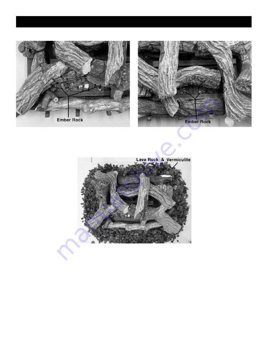
Place ember rocks on ember plates. (Warning: Do not place ember rocks on the burner tubes).

Step (6) 

Place lava rock on the bottom of the fire box

surrounding the burner system. Sprinkle vermiculite over top
of the Lava Rock.

LOGC31 PLACEMENT for GLMVF40 BURNER GRATE

Содержание GLMVF40MVN

Страница 1: ...stallation adjustment alteration service or maintenance can cause injury or property damage Refer to this manual for correct installation and operational procedures For assistance or additional inform...

Страница 2: ...2...

Страница 3: ...wn between each Be aware during log and firebox paint curing that a white deposit may be developing on the inside of the glass doors It is important to remove this white deposit from the glass doors w...

Страница 4: ...e Ventilation 21 Determining Air Flow for Firebox Location 21 Ventilation Air from Inside Building 23 Ventilation Air from Outdoors 24 Installing Gas Line 25 Installing MVFB 4040 Burner System 26 Clea...

Страница 5: ...5 10 1 6 3 5 32 0 25 MVFBL4040MVP Millivolt Liquid Propane 26 000 34 000 11 13 6 3 10 50 Full Open Right Hand Burner MVFBR4040MVN Millivolt Natural Gas 26 000 38 000 5 5 10 1 6 3 5 32 0 25 MVFBR4040M...

Страница 6: ...e used or stored under dusty conditions 10 Surface of appliance becomes very hot when operating Keep children and adults away from hot surface Appliance will remain hot for some time after shutdown Al...

Страница 7: ...d circulating air passageways of the appliance be kept clean 30 Warning Any change to this heater or its controls can be dangerous 31 Must be installed by a licensed gas tter in the Commonwealth of Ma...

Страница 8: ...ru top View Without 2 x 4 Framing See Thru Top View using 2 x 4 Framing Island Top View PLACEMENT AND FRAMING Note When not using nailing tabs you may place Heatshield directly against existing wall a...

Страница 9: ...orner Polish Brass Two Sets MGCKAB Grill Kit Corner Antique Brass Two Sets MGCKCR Grill Kit Corner Chrome Two Sets MVF40PCK Panel Kit for Corner Kit Black Two Sets BURNER SYSTEM LOG SET REQUIRED FOR M...

Страница 10: ...ets BURNER SYSTEM LOG SET REQUIRED FOR MVF40 FIREBOX OPTION 1 GLMVF40MVN Vent Free Multiview Burner System Millivolt Valve 38 000 BTU HR Natural Gas GLMVF40MVP Vent Free Multiview Burner System Milliv...

Страница 11: ...can choose a Right Burner if a is notated beside part number FRAMING PARTS continued BURNER SYSTEM LOG SET REQUIRED FOR MVF40 FIREBOX OPTION 1 GLMVF40MVN Vent Free Multiview Burner System Millivolt Va...

Страница 12: ...ch as tile marble and brick may overlap any facing on the appliance but should never cover any necessary openings like louvered grills WARNING Do not allow any combustible materials to overlap the reb...

Страница 13: ...ce from the bottom of rebox to the oor is 0 inches Bottom of unit must be ush with top of combustible oor covering D Clearance from side of replace to enclosure is 0 inches E Clearance from top of rep...

Страница 14: ...with the vent free gas log heater that is being installed IMPORTANT When nishing your rebox combustible materials such as wall board gypsum board sheet rock drywall plywood etc may be butted up next...

Страница 15: ...NING Any changes to this heater or its controls can be dangerous CAUTION Use new black pipe only Internally tinned copper tubing can be used in some areas when permitted by local codes Only use pipe o...

Страница 16: ...is installed without nailing tabs the unit must be secured to the oor using the holes located in the bottom of the replace FIREPLACE ASSEMBLY 1 Mount Door Cover on one end Figure 6 Position Door Cove...

Страница 17: ...in a non conventional manner not using 2x4 framing the nailing tabs may be removed and the Heat Shields may be placed directly against a combustible wall or partition When the unit is installed withou...

Страница 18: ...e bottom of the replace FIREPLACE ASSEMBLY 1 To mount Door Cover Figure 10 Position Door Cover over opening as shown in diagram and using 6 self tapping screws secure onto replace Check to see that do...

Страница 19: ...aced directly against a combustible wall or partition When the unit is installed without nailing tabs the unit must be secured to the oor using the holes located in the bottom of the replace FIREPLACE...

Страница 20: ...ugh 18 depending on type of installation eg SEE THRU ISLAND PENINSULA CORNER AND BAY PENINSULA Follow all clearances to combustibles in this manual and see below for installation of the Bottom Firebox...

Страница 21: ...atmosphere have a continuous water vapor retarder with a rating of one perm 6 x 10 11 per pasec m2 or less with openings gasketed or sealed and b weather stripping has been added on openable windows...

Страница 22: ...oors and vents to the outdoors 4 Compare the maximum Btu Hr the space can support with the actual amount of Btu Hr used __________________ Btu Hr maximum the space can support __________________ Btu H...

Страница 23: ...u can also remove doors into adjoining rooms Follow the National Fuel Gas Code NFPA 54 ANSI Z223 1 Section 5 3 Air for Combustion and Ventilation for required size of ventilation for required size of...

Страница 24: ...12 of the ceiling and one within 12 of the oor Connect these items directly to the outdoors or spaces open to the outdoors These spaces include attics and crawl spaces IMPORTANT Do not provide openin...

Страница 25: ...ssure at the pressure test point which is located on the side of the gas control near the pilot outlet Make sure that the pressure tap is completely closed after checking gas pressure The pressure sho...

Страница 26: ...agrams or failure to use only part speci cally approved with this heater may result in property damages or personal injury CLEANING AND SERVICING OF BURNER ODS PILOT It is recommended to annually insp...

Страница 27: ...1 and position Log 2 up against Log 4 NOTE LOG 5 IS TO BE POSITIONED ON THE NON FLAME SIDE Crushed Rock Installation Place crushed rock onto firebox bottom making sure not to place any rock onto the b...

Страница 28: ...meter of the burner Do not place on middle burner as illustrated Care should be taken not to block burner ports Step 2 Take Log 4 and place onto burner using the two log tabs located on burner pan as...

Страница 29: ...5 rests on the shape of Log 4 Log Pin Step 5 Place Log 3 onto both Log 1 and Log 5 using the log pins as a guide Log Pin Step 6 Place Log 2 onto both Log 1 and 4 using the log pins as a guide Ensure...

Страница 30: ...ation 4 Tilt burner assembly so valve is at an angle to the Fireplace and lower into position 5 Center Burner assembly inside Fireplace and fasten with 2 supplied screws 6 Place 8 Grate Bars into Burn...

Страница 31: ...hole on Log 3 Position hole on Tab 3 as shown Do not place log over the center burner tube Step 3 Locate the 2 mounting holes on the bottom of Log 4 and position them onto Tabs 4A and 4B Place V area...

Страница 32: ...ber plates Warning Do not place ember rocks on the burner tubes Step 6 Place lava rock on the bottom of the re box surrounding the burner system Sprinkle vermiculite over top of the Lava Rock LOGC31 P...

Страница 33: ...33 CAUTION Do not wire 120 Volt power to Millivolt switches or thermostats MILLIVOLT LIGHTING INSTRUCTIONS...

Страница 34: ...tom inside corners of post there are vertical slots as shown in Ref A B 2 Grills panels have tabs on both ends To install slide the tabs into slots on one side of post top side up Ref D 3 Clip opposit...

Страница 35: ...1 To install fan locate 8 screws in bottom of replace Ref A Fan and fan shield should always be mounted at the end of the replace with the small clearance shield mounted corner kit peninsula kit see...

Страница 36: ...F P683VE 13 Regulator 1 33VF P245M 14 Connector 1 33VF P683VE 15 Alt Tube 3 16 x 3 1 33VF P316VE 16 COS Valve 820 Nova NG 1 33VF P637SI Ref Description Qty Part 1 Brass Cap Orifice 1 1000 255 2 Brass...

Страница 37: ...8 COS Pilot NG 1 33VF P8214 9 Compression Sleeve 1 33VF P603VE 10 Compression Nut 1 33VF P613VE 11 ALT TUBE 3 16 X 11 5 1 33VF P316VE 12 Connector 1 33VF P683VE 13 Regulator 1 33VF P245M 14 Connector...

Страница 38: ...rol Panel 10 1 1000 216 1000 216 Rocker Switch 11a 1 1000 214 1000 214 Piezo igniter 11b 1 1000 215 1000 215 Pal Nut for Piezo igniter 12 8 39GL 105 39GL 105 Grate Bar 13 1 350 P217SI 350 P217SI 1 1 2...

Страница 39: ...o Sets MGSKPB Grill Kit See Through Polish Brass Two Sets MGSKAB Grill Kit See Through Antique Brass Two Sets MGSKCR Grill Kit See Through Chrome Two Sets MVF40PSK Panel Kit See Through Black Two Sets...

Страница 40: ...Sets ACCESSORIES OPTIONAL Z36SAB Surround Antique Brass Coverage Old Style 33 3 4 H x 39 7 8 W Z36SCR Surround Chrome Coverage New Style 34 1 2 H x 41 1 8 W Z36SPB Surround Polish Brass Coverage New S...

Страница 41: ...FF position Possible Cause Remedy 1 Gas leak 1 Locate and correct all leaks 2 Control valve defective 2 Replace control valve When igniter button is pressed there is a spark at ODS pilot but no igniti...

Страница 42: ...er is damaged 2 Replace burner 3 Gas regulator is defective 3 Replace Gas regulator Slight smoke or odor during initial operation Possible Cause Remedy 1 Vapors from paint or curing process of logs 1...

Страница 43: ...ith service or maintenance h damage repairs inoperation or inefficiency resulting from faulty installation or application i electricity or fuel costs or any increase in electricity or fuel cost whatso...

Отзывы: