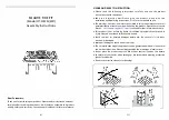
Gas Line Installation
This gas appliance should be installed by a qualified installer in accordance with local building codes and with current CAN/CGA -
B149.1 or .2 installation codes for Gas Burning appliances and equipment in Canada and the National Fuel Gas Code ANSI Z223 in
the U.S.A.
1. The gas pipeline can be brought in through
either the right or the left side of the appliance.
A knockout is provided at either location to allow
for the gas pipe installation and testing of any
gas connection.
2. The gas control inlet is 3/8” NPT. Typical
installation layout for rigid pipe is shown at right.
3. When using copper or flex connector, use
only approved fittings. Always provide a union
so that gas line can be easily disconnected for
burner or fan servicing. See gas specification for
pressure details and ratings.
4. When a vertical section of gas pipe is
required for the installation, a condensation trap
is needed. See CAN/CGA-B149.1 or .2 for code
details.
5. For natural gas, a minimum of 3/8” iron pipe with gas minimum pressure of 4.5” w.c. must be used for supply from the gas meter.
Consult with the local gas utility if any questions arise concerning pipe sizes.
6. A 1/8” NPT plugged tappings are accessible for test gauge connection both on the inlet and outlet of the gas valve.
7. Turn the gas supply ON and check for leaks. DO NOT USE OPEN FLAME FOR THIS PURPOSE. Use an approved leak testing
solution.
8. The appliance and its individual shutoff valve must be disconnected from the gas supply piping system during any pressure
testing of that system at test pressures in excess of 1/2 PSIG (3.5 KPa).
9. The appliance must be isolated from the gas supply piping system by closing its individual shutoff valve during any pressure
testing of the gas sup- ply piping system at test pressures equal to or less than 1/2 PSIG (3.5 KPa).
Gas Specifications
MODELS
ZCVRB60N
ZCVRB60NE
MQZCVRB60NE2
ZCVRB60LP
ZCVRB60LPE
MQZCVRB60LPE2
Fuel
Natural
Propane
Gas Control
Millivolt / IPI
Millivolt / IPI
INPUT
Maximum
35,000 BTU
35,000 BTU
Low
23,000 BTU
28,000 BTU
Orifice Size
(0-4500ft)
#32
#49
Air Shutter
1/16”
1/4”
Gas Inlet Size S.I.T. 820 Nova, 3/8” NPT
Gas Supply Pressure
Minimum
Normal
Maximum
Natural Gas
5.5”
7”
9”
Propane
11”
11”
12”
Manifold Pressure
Natural Gas
Propane
Manifold Pressure High
3.5 IN. W.C./.87
KPa
10 IN. W.C./2.61 KPa
Manifold Pressure Low
1.6 IN. W.C./.40
KPa
6.3 IN. W.C./1.57 KPa
3/8” UNION
1/2” X 3/8” SHUTOFF
VALVE
3/8” NIPPLE
1/2” GAS SUPPLY
NOTE:
The gas line connection may be made of 1/2” rigid pipe or an
Approved Kingsman Flex Connector, such as FP15GC
.
Since some municipalities have additional local codes, it is always best to consult your local authorities and the current CAN/CGA
- B149.1 or .2 installation code in Canada or the National Fuel Gas code ANSI Z223.1 in the U.S.A
Important: Always check for gas leaks with a soap and
water solution. Do not use open flame for leak testing.
For the state of Massachusetts a T-handle gas
shut-off valve must be used on a gas
appliance. This T-handle gas shut-off valve
must be listed and approved by the state of
Massachusetts. This is in reference to the state
of Massachusetts state code CMR238.
Shutoff valves installed in tubing systems shall be rigidly
and securely supported independently of the tubing.
41
Содержание marquis MQZCVRB60LPE2
Страница 47: ...Gas Conversion for Modulator PART C 47...
Страница 61: ...Configuration 1 Basic manual HI LO and manual ON OFF capabilities 61...
Страница 69: ...Proflame 2 Remote Control 69...
Страница 71: ...71...


