Kilowatt Labs Sirius 7100-48-B-2C-M-SD-A-G Скачать руководство пользователя страница 33


Sirius Capacitor Module 

 User Manual  


Model Number -7100-48-B-2C-M-SD-A-G 

This manual is subject to change without notice and at the sole discretion of Kilowatt Labs, Inc.


Kilowatt Labs, Inc. | 

www.kilowattlabs.com


   33 


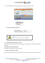
results, and for that the Module needs to be calibrated. But before that please check the following: 


Firstly,  double  check  the  value  with  accurate  meter  (we  suggest  Fluke  multimeter),  if  the  deviation 
between the Module and multimeter is less than ±0.5% it is acceptable. 


Secondly  if  the  deviation  is  more  than  ±0.5%,  the  Module  needs  calibration.  Please  consult  with  your 
Reseller for calibration. 

Q. What could happen when connecting different model of Sirius Module parallel/series together?


A. Modules can be connected in parallel or in series if they will have:


- Same Voltage 
- Same Capacity 
It is possible but not recommended especially connecting old BMS design to the new one. The system might 
get unpredictable during extreme scenarios like Module charge full or low. 
 

Q. Is it possible to connect Sirius Module in parallel with other chemical batteries such as lithium-ion or lead 
acid? 

A. It is possible but not recommended. Make sure the total voltage of each battery is the same as the Module 

and the charging voltage does not exceed the Module’s maximum voltage. The possible drawback is that you 

will not get the total capacity of the chemical battery because extreme voltages are not the same. 
 

Q. If we set the cutoff voltage on the charge controller systems /inverter end to 45V, will that allow the 
Module to sit at idle for longer periods of time to
 avoid an undervoltage situation. 

A. Yes. 


Q. How to check charging/discharging energy of Module?  

A. Please refer to “Overview of SiriusVIEW Application” section in 

SiriusVIEW application manual. 


Q. Why the Module needs twice of power cycle?


 A. When the Module is switched OFF and the SiriusVIEW is still open you have to wait for 10 Sec (since the 
application is still communicating with the Module) before turning ON the Module, or either by terminating 
the SiriusVIEW or by disconnecting the communication cable. 
 

Q. How much is the capacity of the internal storage (SD Card)? 

A. 8GB SD Card is used in the Module which logs 85 bytes of data per 10 seconds. Note that data logging should 
be turned ON before the Module will start logging and data logging is limited to 30 days. After reading the 
data  the  Module will delete  it automatically. By default, data  logging is OFF for firmware  version 2. 0 and 
above. 
 

Q. Do I need to use SiriusVIEW Software? 

A. The Module can work stand-alone without the software however, the software can be used to monitor and 
extract the data & measurement as well as to enhance the performance of the Module.  
 

Q. How do I know if there is firmware issue in the Module?


A. Please refer to SiriusVIEW monitoring software manual Configuration of Module and Software section.  


Q. What kind of issues can happen about firewall and antivirus programs? 


A. There will be no problem as far as the software run as administrator.  


Q. How to calibrate Module parameters?


A.  To  calibrate  Module  parameter  like  (Voltage,  Current,  Temperature,  Energy).  Kindly  consult  with  your 
Reseller for calibration procedure. 


Q. What is the reason if the LED isn’t working at all?


Содержание Sirius 7100-48-B-2C-M-SD-A-G

Страница 1: ...SIRIUS CAPACITOR MODULE User Manual Model number 7100 48 B 2C M SD A G Version 1 0 Release Date July 2019...

Страница 2: ...change without notice While every attempt has been made to make the Manual accurate and up to date users are cautioned that product improvements may cause the Company to make changes to specifications...

Страница 3: ...11 3 Module Installation 16 3 1 Inspection 16 3 2 Safety Gear 16 3 3 Unpacking and Contents Check 17 4 Operation Procedures 17 4 1 Module Configuration 17 4 2 Software Configuration 19 5 Recovery Pro...

Страница 4: ...13 Test Procedures 28 13 1 Round Trip Efficiency Test 28 13 2 Terminal Resistance and Internal Resistance 30 13 3 Test Method for Self Discharge 31 14 FAQs 32...

Страница 5: ...rius Modules are designed to provide years of trouble free operation Proper handling is required to avoid damage to the Module In particular the following precautions should be observed Personal Safet...

Страница 6: ...Do not touch the terminals with conductors while the Module is charged Serious burns shock or material fusing may occur Protect surrounding electrical components from incidental contact When connecti...

Страница 7: ...shipped via Sea please follow the instructions given below Carefully remove the Module from the pallets after cutting the packing strip holding the Modules to the shipping pallets Open the carton box...

Страница 8: ...7100 48 B 2C M SD A G This manual is subject to change without notice and at the sole discretion of Kilowatt Labs Inc Kilowatt Labs Inc www kilowattlabs com 8 2 2 Product Overview 2 2 1Appearance The...

Страница 9: ...Manual Model Number 7100 48 B 2C M SD A G This manual is subject to change without notice and at the sole discretion of Kilowatt Labs Inc Kilowatt Labs Inc www kilowattlabs com 9 2 2 2Mechanical Drawi...

Страница 10: ...or Module User Manual Model Number 7100 48 B 2C M SD A G This manual is subject to change without notice and at the sole discretion of Kilowatt Labs Inc Kilowatt Labs Inc www kilowattlabs com 10 Side...

Страница 11: ...2 2 3Dimension and Weight Width 608mm Length 530mm Height 345mm Weight 130 kg 2 3 Front Panel Description Object Mark Description 1 Circuit Breaker C100A Circuit Breaker 2 2 Bypass Breaker C20A 3 Faul...

Страница 12: ...old fault reset for 5 seconds to toggle the terminal b Hold fault reset for 3 seconds to reset fault if there is are any c We can set the Current reading to zero d Press fault reset button to check th...

Страница 13: ...has been enabled Step 3 To disable cell balancing when current is zero the LCD will display the following message Step 4 After this message appears hold the fault reset button for 5 seconds then when...

Страница 14: ...lowing message This means that the current is now zero To return back to the normal screen press the fault reset button once more or leave the Module idle for 5 seconds 4 LCD Description Once the powe...

Страница 15: ...This is a COMM connector to monitor the Module using the Sirius software FTDi chip is used for this USB 7 COMM Status LED COMM Status LED indicates the communication status LED Status Indication Colo...

Страница 16: ...ocument photograph any damage and report this to your Reseller as well as to the shipping agent immediately Remove the Module from the shipping carton and retain the shipping materials until the unit...

Страница 17: ...w kilowattlabs com 17 3 3 Unpacking and Contents Check Check the contents of the package 1 Sirius Capacitor Module 7 1KWh48VDC 3 USB Cable A B 2 Bolts 2 4 Washers 4 4 Operation Procedures 4 1 Module C...

Страница 18: ...ure below 2 The picture below shows that the Module is turned ON 3 Wait till the LCD screen on the Module displays initial values 4 Be sure you are able to see the terminal status LED OFF 5 Press and...

Страница 19: ...e Configuration To configure SiriusVIEW application please follow the steps below 1 Install the SiriusVIEW application on your system 2 Connect the USB cable to the COMM connector USB slot to start co...

Страница 20: ...ce Auto Pop up dialogs 9 When the connection between PC and Module is established successfully INIT LED will be constantly turned ON 10 For getting measurement press RUN button 11 If there is any prob...

Страница 21: ...c and current range of 1A to 10A will be required 3 Connect the positive terminal of the power supply to the positive terminal of the F12 terminal and negative terminal of the power supply to the nega...

Страница 22: ...overy Maximum Current 10 A Recommended Voltage 44V 54V 6 Connecting the Module in Parallel or in Series The capacity or voltage of the Module can be increased by connecting them in Parallel or Series...

Страница 23: ...rom the respective common point 6 2 Series Connection of Sirius Modules A maximum of 8 Modules can be connected in Series with a Module Combiner Steps to Connect Modules in Series Refer to the Series...

Страница 24: ...arning Message Description Over Current OCD When the Module has an Over current fault the counter counts for 5 seconds and if the current does not drop lower than the cut off and count down has reache...

Страница 25: ...nds When the Module is connected to a load and it reaches the minimum voltage the buzzer alarms electronic switch will shut down and LCD will display the message Over Temperature When the Module has a...

Страница 26: ...nding temperature and ensure the ambient temperature is less than 80 C If not leave the Module to cool till the temperature comes below 80 C Now turn ON the circuit breaker Please Remove Charger Pleas...

Страница 27: ...ntrast can be configured anytime over SiriusVIEW Monitoring application 5 Sirius Module can be used with Power Save Mode this feature can be activated by SiriusVIEW Monitoring application 6 Front pane...

Страница 28: ...0 Shelf Life Shelf life is the life of the Module in years from the date it is manufactured to the time it is first operated The shelf life of supercapacitor cell is 10 years 11 Maintenance The Sirius...

Страница 29: ...Test Current Different current within the maximum limit specified by the test equipment manufacturer can be applied to the test Test Process Step 1 Rest open circuit Record test time test current and...

Страница 30: ...e the voltage between the two terminals of the supercapacitor is During constant current charge and discharge At open circuit voltage the measured supercapacitor voltage is By putting the values equat...

Страница 31: ...e rest t3 I3 V3 Step 4 Rest open circuit 10 seconds Record test time test current and test voltage at the start of the rest t4 I4 V4 Step 5 Discharge Discharge device to one half its rated voltage at...

Страница 32: ...re section in user manual Module is OFF Both of the terminals will not work when the Module is switched OFF Q The Module shows zero current while using unprotected terminal for recovery For Anderson T...

Страница 33: ...w the Module to sit at idle for longer periods of time to avoid an undervoltage situation A Yes Q How to check charging discharging energy of Module A Please refer to Overview of SiriusVIEW Applicatio...

Страница 34: ...please consult with your Reseller Q The Module is showing Contact Service A Contact your Reseller for customer support Q How to update the Firmware A New Firmware is uploaded to https www amberandwase...

Страница 35: ...tically during charging when the cells get unbalanced Note that it is activated only when the Module Voltage reaches 52 V Q Can balancing and auto balancing options be activated at a same time A Yes Q...

Отзывы: