


Sirius Capacitor Module
–
User Manual
Model Number -7100-48-B-2C-M-SD-A-G
This manual is subject to change without notice and at the sole discretion of Kilowatt Labs, Inc.
Kilowatt Labs, Inc. |
10
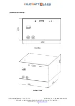
Side View
Top View
Sirius Capacitor Module
–
User Manual
Model Number -7100-48-B-2C-M-SD-A-G
This manual is subject to change without notice and at the sole discretion of Kilowatt Labs, Inc.
Kilowatt Labs, Inc. |
10
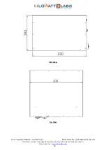
Side View
Top View


