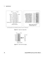
Switch Configuration
2
Keysight 87406Q Operating and Service Manual
15
RF path selection
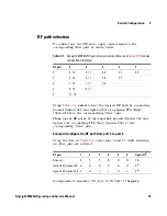
To connect any two RF ports, apply control signal to the
corresponding drive pins as shown below.
Using
Table 2- 1
,
select
(close) the desired RF path by connecting
ground (Option 024 and Option 100) or applying TTL "High"
(Option T24) to the corresponding "drive" pins.
Clear
(open) RF paths by disconnecting ground (Option 024 and
Option 100) or applying TTL "Low" (Option T24) to the
corresponding "drive" pins.
Example: Configure the RF path from port 2 to port 5
Using the data in
Table 2- 1
, select pins 5 and 11 while ensuring
no other pins are selected.
Table 2-1
Keysight 87406Q RF port drive pin control data (see
Figure 3-5
for drive
connection diagrams)
RF port
6
5
4
3
2
1
3, 13
3, 11
3, 9
3, 7
3, 5
2
5, 13
5, 11
5, 9
5, 7
3
7, 13
7, 11
7, 9
4
9, 13
9, 11
5
11, 13
RF port
1
2
3
4
5
6
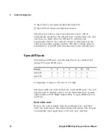
Open all
[1]
Drive pin
3
5
7
9
11
13
16
Option 024, Option 100
U
G
U
U
G
U
X
[2]
Option T24, Option 100
L
H
L
L
H
L
X
[2]
U = Ungrounded, G = Grounded, L = TTL "Low", H = TTL "High", X = Negligable
Содержание 87406Q
Страница 1: ...Keysight 87406Q Low PIM Coaxial Matrix Switch Operating and Service Manual ...
Страница 2: ......
Страница 3: ...Keysight 87406Q Operating and Service Manual 1 ...
Страница 12: ...10 Keysight 87406Q Operating and Service Manual 1 Introduction This page is intentionally left blank ...
Страница 30: ...28 Keysight 87406Q Operating and Service Manual 3 Specifications This page is intentionally left blank ...

