14
Keysight 87406Q Operating and Service Manual
2
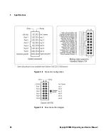
Switch Configuration
Driving the Switch
DC power connection
•
Connect pin 1 to supply (+20 VDC to +32 VDC)
•
Connect pin 15 to chassis ground to enable the electronic
position indicating circuitry and drive logic circuitry.
N O T E
Pin 15 must always be connected to ground to enable the electronic
position-indicating circuitry and drive logic circuitry.
C A U T I O N
If pin 15 is not connected to power supply ground, catastrophic failure will
occur.
N O T E
After the RF path is switched and latched, the drive current is interrupted by the
electronic position-sensing circuitry. Pulsed control is not necessary, but if
implemented, the pulse width must be 15 ms minimum to ensure the switch is
fully latched.
Содержание 87406Q
Страница 1: ...Keysight 87406Q Low PIM Coaxial Matrix Switch Operating and Service Manual ...
Страница 2: ......
Страница 3: ...Keysight 87406Q Operating and Service Manual 1 ...
Страница 12: ...10 Keysight 87406Q Operating and Service Manual 1 Introduction This page is intentionally left blank ...
Страница 30: ...28 Keysight 87406Q Operating and Service Manual 3 Specifications This page is intentionally left blank ...


