


6
1
Name: Basis
KEB COMBIVERT F4-C
6
09.04.99
©
KEB Antriebstechnik, 1999
All Rights reserved
Functional Description
Chapter
Section
Page
Date
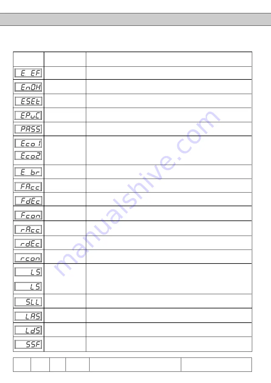
Operating and Appliance Displays
Display
Bus value ru.0
Meaning
Error code Pr.5
31
Error External Fault (external error ); is triggered, when a digital input is
programmed as external error input (di. 3...di.10 = 6) and trips.
36
Error no Over Heat (error: no overheating); inverter and motor overheating („E.OH“
or „E.dOH“) are not present. After reset ready for operation.
39
Error SEt (set selection error); occurs when trying to select a locked parameter
set.
49
Error Power unit Code invalid; (error: power section identification invalid) ; during the
initialization phase the power section was not identified or detected as inadmissible.
50
This message is displayed after successfull copying of parameter sets.
54
This message is displayed when there are overflows and inadmissible limitings.
This error occurs, if in any section of the speed or frequency calculation the speed
is > 9999 rpm or the frequency is > 409,6 / 819,2 Hz.
56
Braking control on (see chapter 6.9.6); occurs, if the load during a start is <
minimum load level (Pn.58).
64
Forward Acceleration, (forward acceleration); drive is in the state of acceleration
with direction of rotation forward (clockwise rotation).
65
Forward dECeleration, (forward deceleration); drive is in the state of deceleration
with direction of rotation forward (clockwise rotation).
66
Forward constant, (constant run forward); drive has reached the adjusted
frequency and runs constant forward (clockwise rotation).
67
reverse Acceleration, (reverse acceleration); drive is in the state of acceleration
with direction of rotation reverse (counter-clockwise rotation).
68
reverse dECeleration, (reverse deceleration); drive is in the state of deceleration
with direction of rotation reverse (counter-clockwise rotation).
69
reverse constant, (constant run reverse); drive has reached the adjusted frequency
and runs constant reverse (counter-clockwise rotation).
70
Low Speed; control release is switched but no direction of rotation is adjusted,
i.e. modulation disabled; output voltage = 0V; drive uncontrolled.
The point in the display means that the inverter is operated by way of the
DRIVECOM profile parameters (ud.5 = 1 or 2). According to state diagram in
condition „ready to start“ or „switched on“.
71
StaLL; Stall function active; the stall function protects the inverter against overload
during constant operation; the max. current is defined with (Pn.13).
72
Load Acceleration Stop - function active (acceleration stop); protects the inverter
against overcurrent errors during the phase of acceleration (also refer to Pn.5).
73
Load deceleration Stop - function active (deceleration stop); protects the inverter
against overvoltage errors during deceleration (also refer to Pn.6).
74
Speed Search function active; is displayed during the phase in which the inverter
synchronises to a coasting motor (see Pn.7).
9000h
1000h
6300h
6100h
-
-
-
-
-
-
-
-
-
-
-
-
-
-
-


