


9
ANTRIEBSTECHNIK
6
9
9
KEB COMBIVERT F4-C
Name: Basis
29.01.98
6
ANTRIEBSTECHNIK
Section
Page
Date
©
KEB Antriebstechnik, 1997
All Rights reserved
Chapter
Functional Description
Special Functions
A
B
A
B
A
B
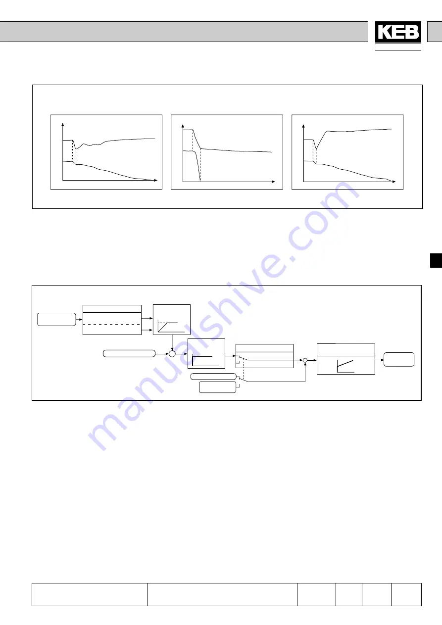
f,U
f,U
t
t
f,U
t
A: DC-lin voltage
B: Output frequency
Jump Factor
(Pn.38)
By means of the jump factor the automatically determined starting jump can be adapted
to the respective application.
In case the jump factor is too low, the inverter trips to UP!
In case the jump factor is too high, the inverter runs into the hardware current limitation.
The control cannot work correctly, thus causing a wrong calculation of the active
current!
Fig. 6.9.3.c Adjustment of Jump Factor
Optimal setting
Jump factor too low
Jump factor too high
Fig. 6.9.3.d Power-Off Control
Power-Off Control
1. Buffering of short-time power failures:
The drive shall be kept running for as long as possible with the available energy,
in order to continue the operation upon voltage recovery. This is particularly
suited for large flywheel masses. The DC-link voltage is the controlled variable
onto which it is regulated with the setpoint value as manipulated variable.
2. Emergency Stop:
The drive shall be brought to a standstill before the inverter switches off. The
active current is the control variable onto which it is regulated with the setpoint
value as manipulated variable
First the setpoint DC-link voltage is adjusted with Pn.42. This is the value with which
the regulation takes place.
Pn.42 DC-link set value
Automatic (199)
Setting 200...800V
Automatic DC-
link set value
DC-link set
value ramp
DC-link actual value
+
-
Pn.34 DC-link /
P-component
Pn.18 Braking forque
0 (default)
0,1...100,0%
DC-link difference
measured
active current
+
-
Pn.36 Iw P-component
Pn.37 Iw I-component
Delta-
frequency


