background image


-6-


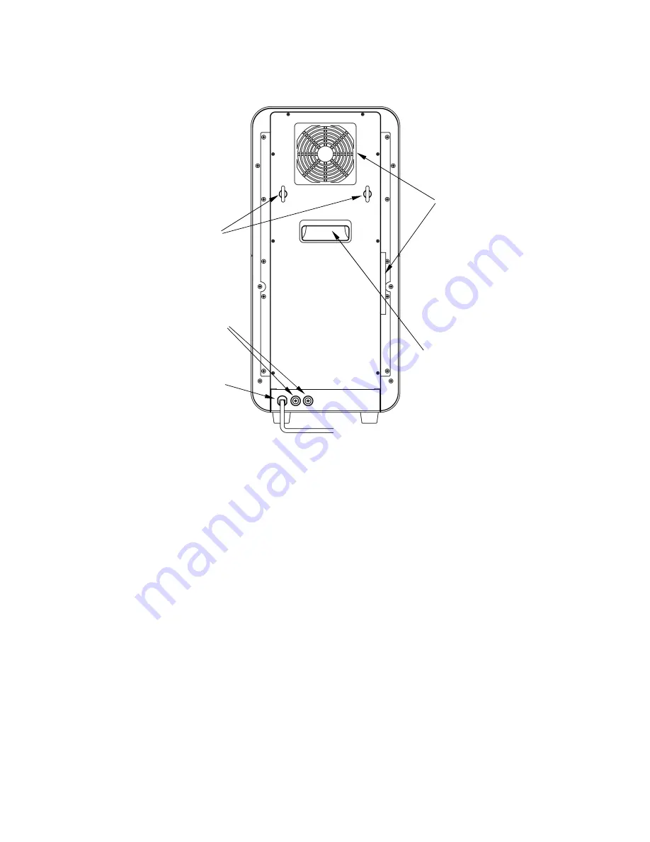
Back View 


                                                                      Cooling Fan 


                      Eyebolt 


                      Line Fuse 


Handle 


                  Power Cord 


    Line Fuse   

Φ 6.4-20A glass fuse. 

    Cooling Fan 

Two fans on the back and left side of the unit. 


Содержание Zircom

Страница 1: ...stand the capabilities and proper usage for this machine Please keep this manual in an easily accessible location for future reference Contents Safety Precautions 1 Standard Accessories 4 Descriptions of Component Parts 5 Preparations before use 7 Operation 8 How to use 9 Periodic Maintenance 16 Error Messages 17 Specification 18 W1016100 A ...

Страница 2: ...vent injuries and loss on material resources Please read them carefully prior to your actual machine operation Failure to follow or ignorance of the directions may cause severe injury or death Failure to follow or ignorance of the directions may cause injuries or damages to material properties This mark means prohibited actions as shown inside or around it The illustration on the left means Do not...

Страница 3: ... the instrument Doing so may cause internal temperature increase and cause fire or malfunction of the unit Plug to the outlet of the designated voltage described in the main specifications Use of other voltage may cause fire or shock Keep the unit away from other equipment and walls Leave minimum of 20cm of space around the unit Do not place anything on the top of the unit to prevent temperature i...

Страница 4: ... or breakdown may occur Do not use the accessories and consumables we do no recommend Breakdown or fire may occur Use the heat resistant glove and tongs to take the firing tray in and out because inside of furnace may be high temperature Do not touch around the furnace firing table during heating up because of high temperature If any operations is required during heating up use the heat resistant ...

Страница 5: ...t Contact our technical support team if there is any damage Cracked insulator inside the muffle chamber is normal This is not defected Quick Firing Stand 1pc Firing Tray S 3pcs Quick Firing Tray 1pc Quick Firing Tray Stand 1pc Firing Cover 1pc Quick Firing Cover 1pc Firing Beads Instruction Manual 1 booklet We recommend you to save the carton and all packing materials for future use ...

Страница 6: ...ck Firing Stand Place to put quick firing tray stand Firing Table Table to place quick firing stand and it moves up and down Power Switch Power switch for the unit LCD Panel LCD panel allows you to check programs settings and operate the unit Operation Key F1 F4 Up Down Left Right Start Stop and Table Up Down are used to Operate the unit SD Card Slot The slot allows you place SD card to backup and...

Страница 7: ... 6 Back View Cooling Fan Eyebolt Line Fuse Handle Power Cord Line Fuse Φ 6 4 20A glass fuse Cooling Fan Two fans on the back and left side of the unit ...

Страница 8: ...gle phase 20A and grounding Installation of Quick Firing Stand Power on the unit by pressing the power switch button After Standby mode appears press the button to bring down the table Put the provided quick firing stand on the inside of 4 guide pins of firing table Put the quick firing tray stand on the groove Unloaded Muffle Firing There may be moisture in the firing tray the firing cover and fi...

Страница 9: ...iring operation Key Move the table up down Operation Modes The unit has 7 modes for various functions Standby Mode Standby mode before firing After powering on the unit will enter this mode P9 Program Mode Inputs a program for each course number P10 Firing Mode Displays temperature and firing process during firing process P12 Copy Mode Copies a program to a different course P14 Default Mode Sets e...

Страница 10: ...Go to copy mode P14 F3 Default Set Go to default mode P14 F4 Maintenance Go to maintenance mode P15 Up Down Key Change course Fast forward by holding the key longer Left Right Key Invalid START STOP Key Start firing and go to firing mode P12 Up Key Key used to move the table up Down Key Key used to move the table down Caution When muffle temperature is high for safety purpose table moving down is ...

Страница 11: ...0 or above the table moves to 0 automatically 0 Buzzer Type 0 5 5 types of sound 0 is no sound 0 Table Position Table position affects temperature inside the muffle Position 0 completely seals the furnace to quickly rise furnace temperature and position 2 3 4 and 5 give space between the furnace and the table to quickly decrease the furnace temperature We recommend you to set the table at the appr...

Страница 12: ... 0 3 1500 2 00 0 4 400 1 30 0 5 300 1 00 1 Programmed Start temperature for Zircom is 20 C 1 Turn on the power to go to the Standby Mode 2 Press button to choose the course number 98 3 Press F1 key to enter the Program Mode 4 Press to move to Course Name 5 Input the Course Name ZIRCOM by using F3 F4 key and 6 Press to move back to STEP 1 7 Input 1000 by using F3 F4 key 8 Press to adjust Time then ...

Страница 13: ...g stand and the muffle will be hot Be sure use the tongs and heat resistant glove when placing the firing tray onto the quick firing stand Press START STOP key to start firing Firing Mode When firing starts the display turns to Firing Mode and shows furnace temperature progress the remaining time Display Course Course that is in process Course Name Name of the course that is in process Temperature...

Страница 14: ...ng and return to standby mode It is enabled when you press for about 1 second Editing of Running Program 1 Go to Program Mode 2 Press F1 key while pressing the key 3 Use keys to adjust the program 4 Press F2 key OK to return to Program Mode Press the OK key to go to Stand by mode If set to a range of 1 100 the temperature of the final STEP table does not decrease while the top level firing at the ...

Страница 15: ...mode is used to set buzzer volume temperature correction value temperature unit Enter Default Mode During Standby Mode press Default key The screen displays the following screen Setting of each item in the default mode Change the value to move the item by pressing the up or down arrow keys press the key Setting the buzzer volume 4 stages Consumption Small Medium Large Key Sound Default is Small Vo...

Страница 16: ...ful when applying periodic maintenance or when the unit is in need of service Enter Maintenance Mode Press Maintenance key in Standby Mode to display the following screen Descriptions of Maintenance Mode Total Running Time Total running time since purchase Total Firing Cycle Total number of firing cycle since purchase Above 1300 Total firing time above 1300 Note the number of firing It is erasable...

Страница 17: ...he SD card File name will be saved as ZRM_MNT csv In a case of troubleshooting please send this date to our technical support team VIA e mail Importing Firing Program from SD card to Zircom Press F4 key to import data from the SD Card In order to import a Firing Program data from SD card to the unit you must create a program file named ZRM_PRG csv on your PC and save it on your SD Card Periodic Ma...

Страница 18: ... occurs during lifting the firing furnace No 5 Heater disconnection abnormality Error5 is displayed when heater is broken Please replace it with a new muffle No 6 Thermocouple Error Error 6 is displayed when the thermocouple is short circuited or disconnected No 8 Memory Error Error 8 is displayed if the memory content is corrupted or lost by abnormal or excessively loud noise The unit also shows ...

Страница 19: ...ude 2000 meter and under Pollution Degree 2 Over voltage Category Ⅱ Maximum Temperature 1600 Program Memory Capacity 100 programs Safety Function Cooling Fan Abnormal temperature monitoring circuit 10 abnormal operation detection apparatuses Accessories Quick Firing Stand 1pc Firing Tray S 3pcs Quick Firing Tray 1pc Quick Firing Tray Stand 1pc Firing Cover 1pc Quick Firing Cover 1pc Firing Beads 1...

Отзывы: