19
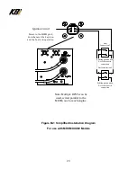
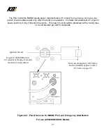
The PLC inside the MKSM needs power at pin four from a source, such as the key-switch, that
provides power only when the boat is in operation. See Figure A1.
Example of existing key-switch.
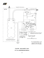
Figure A1: Typical Boat Key-Switch Schematic
For use with
MKSMXXX00 Models
“S” Terminal Power
To Pin 3 of MKSM
Note: See figure A2
for alternate
source.
Note: An emergency start button
Can be installed at pins 1 and 2
See note on page 18.
Power to the
MKSM pin 4,
For whenever
the key is on
and the boat is
in operation.
Содержание KAPower MKSM Series
Страница 10: ...10 Figure 2 Typical Cable Installations ...
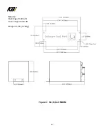
Страница 11: ...11 Figure 3 Six 6 Cell MKSM Material Shell 16ga SS 304 2B Cover 18ga SS 304 2B Weight 21 5lb 9 75Kg ...
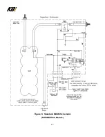
Страница 17: ...17 Figure 6 Standard MKSM Schematic MKSMXXX00 Models ...
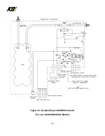
Страница 28: ...28 Figure C3 Multiple Engine MKSM Schematic For use with MKSMXXX01 Models ...

