13
4.3 General Wiring Installation Procedure
The following is the standard MKSM installation method. However, many vessels will use a
variation of this method. After reading the Theory of Operation below, see the following
sections if any of these apply to your vessel:
Installation Variation #1 found on page 18. For vessels using a push button, or key-switch for
single engine starting.
Installation Variation #2 found on page 21. For vessels using push button or rocker switch
starting with multiple engines.
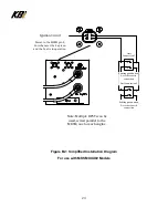
Installation Variation #3 found on page 25. For vessels using a keypad, or digital switching for
engine starting. Also used for boats with multiple engines not using the DPST installation
method.
NOTE: Not all scenarios and installation methods are covered in this document. If your
application does not match any identified in this document, please contact KBI
for assistance.
Theory of Operation, Explaining how the MKSM Module Works:
Once installed and wired properly, the LED on the end-faceplate of the MKSM will be
illuminated green whenever the MKSM contactor relay is closed. When the LED is illuminated,
the contactor is closed; the KAPower Module is running parallel with the vehicle, vessel, or
equipment batteries and electrical system.
Pressing the DPST switch closes the contactor inside the MKSM enclosure, using power from
the KAPower module, regardless of the state of charge of the vessel or equipment’s batteries.
Pressing the DPST switch also engages the cranking motor circuit, just as if the key switch to
the crank/start position had been turned, or the vehicle’s or vessel’s start button (if so
equipped) had been pressed. As such the DPST switch is wired in parallel with the existing
starting system. This is done by wiring and using the recommended electrical circuit,
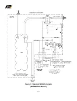
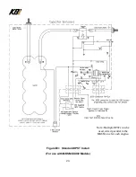
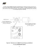
displayed on the schematics in Figure 5 (page 15), and Figure 6 (page 17).This creates a
parallel circuit with the OEM (Original Equipment Manufacturer) electrical circuit, allowing both
the MKSM and the OEM cranking motor circuit to be engaged, simultaneously. Once the
engine starts, the Programmable Logic Controller (PLC) inside the MKSM monitors the
condition of the KAPower Module, and will close or open the contactor relay inside the MKSM,
based on the preprogrammed parameters inside the PLC. When the engine is stopped, the
equipment is turned off, the contactor opens and the KAPower module remains isolated,
waiting for the next engine-starting event, when the DPST switch is pressed.
Содержание KAPower MKSM Series
Страница 10: ...10 Figure 2 Typical Cable Installations ...
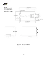
Страница 11: ...11 Figure 3 Six 6 Cell MKSM Material Shell 16ga SS 304 2B Cover 18ga SS 304 2B Weight 21 5lb 9 75Kg ...
Страница 17: ...17 Figure 6 Standard MKSM Schematic MKSMXXX00 Models ...
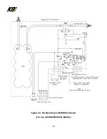
Страница 28: ...28 Figure C3 Multiple Engine MKSM Schematic For use with MKSMXXX01 Models ...

