27
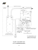
The PLC inside the MKSM needs power (approximately 2.5 amps) from a source, such as a key
switch, that provides power only when the boat is in operation. Consider this additional 2.5 amps of
power and how it may influence the source. This new circuit should be protected with a 5-amp fuse
or circuit breaker per ABYC standards.
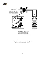
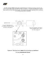
Figure C2: Power Sources for MKSM Pin 4 and Emergency Start Button
For use with MKSMXXX01 Models
Note: An emergency start button
Can be installed at pins 1 and 2.
See note on page 25.
Power to the MKSM pin 4,
for whenever the key is on and
the boat is in operation.
Ignition Circuit
Содержание KAPower MKSM Series
Страница 10: ...10 Figure 2 Typical Cable Installations ...
Страница 11: ...11 Figure 3 Six 6 Cell MKSM Material Shell 16ga SS 304 2B Cover 18ga SS 304 2B Weight 21 5lb 9 75Kg ...
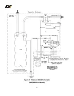
Страница 17: ...17 Figure 6 Standard MKSM Schematic MKSMXXX00 Models ...
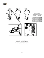
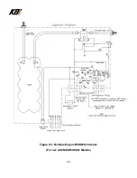
Страница 28: ...28 Figure C3 Multiple Engine MKSM Schematic For use with MKSMXXX01 Models ...


