


29
Part 3 - Con
trol
water outlet setting temperature. In a combination system, the compressor of master unit is controlled according total
water outlet temperature and water outlet setting temperature, the compressor of the slave unit is controlled according
to water inlet and water outlet temperature. Both in a single system and combination system, the compressor speed is
limited by the inverter module temperature (Tf), ambient temperature, discharge temperature and air side heat exchanger
refrigerant total outlet temperature (Tz/7).
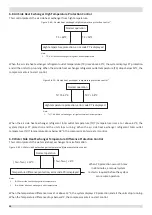
In heating mode: In a single system, the compressor speed is controlled according to the water outlet temperature and
water outlet setting temperature. In a combination system, all compressors are controlled according to the total water
outlet temperature and the water outlet setting temperature. Both in a single system and combination system, the
compressor speed is limited by inverter module temperature (Tf), ambient temperature, discharge temperature, discharge
pressure.
5.3 Compressor Step Control
The running speed of six-pole compressors in rotations per second (rps) is one third of the frequency (in Hz) of the
electrical input to the compressor motor. The frequency of the electrical input to the compressor motors can be altered at
a rate of 1Hz in two seconds.
5.4 Water pump select control
For 30kW and 60kW units model
When the dial switch S12_2 on the main PCB is switched ON, the system runs “one small pump per unit” mode, when
S12_2 is switched OFF, the system runs “one large pump controlled by master unit” mode.
■
One pump control: only the master unit output pump signal, no pump signal output on the slave units.
■
Multiple pump control: output pump signal on all units.
■
S12_2 in one system must be switched to the same position or not error code FP will be displayed.
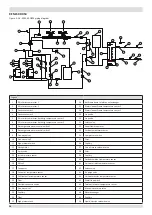
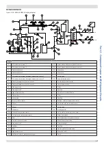
5.5 Four-way Valve Control
The four-way valve is used to change the direction of refrigerant flow through the water side heat exchanger in order to
switch between cooling and heating operations. Refer to Figures 2-3.1 ,2-3.2, 2-3.3, 2-3.4, 2-3.5 in Part 2, 3 “Refrigerant
Flow Diagrams”.
During heating operation, the four-way valve is on; during cooling and defrosting operation, the four-way valve is off.
5.6 Electronic Expansion Valve Control
For 30kW and 60kW units model
The position of the electronic expansion valve (EXV) is controlled in steps from 0 (fully closed) to 480 (fully open).
■
At power-on:
■
The EXV first closes fully, then moves to the standby position (352 (steps)). After 30seconds the EXV moves to an
initial running position, which is determined according to the operating mode and outdoor ambient temperature.
■
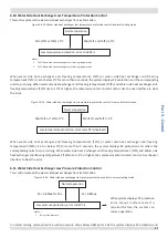
When the unit operate in cooling mode, after 60 seconds, the EXV is controlled according to suction superheat, water
inlet temperature and compressor frequency.
■
When the unit operates in heating mode, after a further 60 seconds, the EXV is controlled according to discharge
superheat and compressor frequency, and uses the suction temperature, air side heater exchanger temperature,
discharge temperature to modify the control.
■
When the outdoor unit is in standby:
• The EXV is at position 352 (steps).


