


100
4.22 F0 Troubleshooting
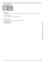
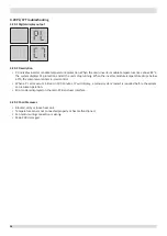
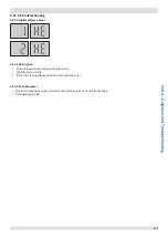
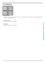
4.22.1 Digital display output
In the error code, 1 representing compressor system A and 2 representing compressor system B.
4.22.2 Description
▪ 1F0 indicates a communication error between the main control chip and the compressor A inverter driver chip.
▪ 2F0 indicates a communication error between the main control chip and the compressor B inverter driver chip.
▪ All units stop running.
▪ Error code is only displayed on the unit with the error.
4.22.3 Trigger / recover condition
▪ Trigger condition: Main control chip and inverter driver chip cannot communication for 2 minutes.
▪ Recover condition: Communication go back to normal.
▪ Reset method: Resume automatically.
4.22.4 Possible causes
▪ Incorrect compressor inverter module address setting.
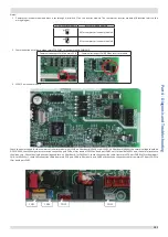
▪ Loosened communication wiring from the main PCB to
the inverter module.
▪ Bridge rectifier damaged.
▪ Main PCB damaged.
▪ Compressor inverter module damaged.
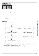
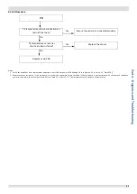
4.22.5 Procedure
F0 error
Compressor inverter module address
setting is incorrect
No
No
No
No
Communication wire from outdoor main
PCB CN65 to inverter module CN8/ CN9
is loosened
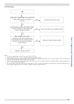
2
Both LED1 and LED2 on inverter module
are off when power on
3
Replace the outdoor main PCB, is the
malfunction solved?
Replace the inverter module
Reset the compressor inverter
module address via dial switch
S7 on inverter module
1
Reconnect the
communication wire
Check the power supply
circuit 4
Normal
Yes
Yes
Yes
Yes