

-
7
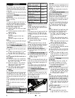
Lift the cleaning head.
Loosen the lock of the wiper flap.
Push the bearing lid down and remove.
Pull out the brush roller.
Note
: The brush rollers must be re-
placed when the bristle length has
reached 10 mm.
Insert a new brush roller.
Reassemble the bearing lid in the re-
verse sequence.
Repeat process on the opposite side.
Lift the cleaning head.
Press the pedal for changing the brush-
es downward beyond its resistance.
Pull the disc brush out of the side below
the cleaning head.
Hold the new disc brush under the
cleaning head, push upward and lock.
Push the appliance forward about 2 m
so that the steering rollers point toward
the rear.
Press the pedal for lowering the clean-
ing head downwards slightly and then
move it to the left. This unlocks the ped-
al. Release the pedal slowly upwards.
The lift arm of the cleaning head will be
lowered.
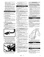
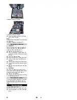
1 Spring element
2 Locking pin
3 Terminal strip cover
4 Lock of safety pin
5 Excenter lever
Remove the terminal strip cover.
Place the cleaning head halfway in front
of the appliance.
Connect the mains supply cable of the
cleaning head to the appliance.
Attach the terminal strip cover.
Connect the hose couplers on the
cleaning head to the hose on the appli-
ance.
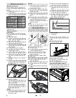
1 Spring element
2 Push handle
Insert the push bow into the cleaning
head intake.
Push the spring elements down and
lock them into place.
1 Excenter lever
2 Locking pin
Open the excenter lever of the slideable
intake on the lift arm.
Press the cleaning head all the way
against the push handle.
Note
: The less play the cleaning head
has after being installed, the less vibra-
tion will occur during cleaning.
Move the intake and insert the safety
pin and lock it into place.
Close the excenter lever.
Swivel the water reservoir all the way
down, check the lock.
The removal will take place in the opposite
order of the installation.
몇
CAUTION
When the cleaning head is removed, the
stability of the appliance can be compro-
mised; ensure a safe stance.
Possibly support the rear to prevent tipping.
Please observe the following warning notes
when handling batteries:
DANGER
Risk of explosion. Do not place tools or the
like on the battery, i.e. on the terminal poles
and cell connectors.
Risk of injury. Ensure that wounds never
come into contact with lead. Always clean
your hands after having worked with batter-
ies.
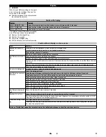
* Appliance requires 2 batteries
** Appliance requires 4 batteries
1)
Complete set (24 V/105 Ah) incl. connect-
ing cable, order no. 4.035-373.0
2)
Complete set (24 V/170 Ah) incl. connect-
ing cable, order no. 4.035-388.0
3)
Complete set (24 V/180 Ah) incl. connect-
ing cable, order no. 4.035-387.0
4)
Complete set (24 V/180 Ah) incl. connect-
ing cable, order no. 4.035-440.0
Push the appliance forward about 2 m
so that the steering rollers point toward
the rear.
Lower the cleaning head.
Empty the fresh and waste water tank.
Loosen the tank lock and tilt the tank
upwards.
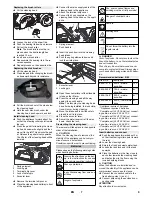
Place the batteries in the tray close to
each other towards the cleaning head
and fasten them to the floor using the
included holding blocks.
몇
CAUTION
When the batteries are installed and re-
moved, the stability of the appliance can be
compromised; ensure a safe stance.
Connect the connection cable to the
free battery poles (+) and (-).
Connect pole using the enclosed con-
necting cable.
ATTENTION
Pay attention to correct poles.
Replacing the brush rollers
Replacing the disk brushes
Install cleaning head
Dismantling the cleaning head
Batteries
Observe the directions on the bat-
tery, in the instructions for use and
in the vehicle operating instructions
Wear eye protection
Keep children away from acid and
batteries
Danger of explosion
Fire, sparks, naked flames and
smoking must be strictly avoided
Danger of chemical burns
First aid
Warning note
Disposal
Do not throw the battery into the
regular waste
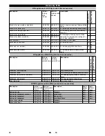
Recommended batteries, B 60
Order No.
Description
6.654-141.0
1)
105 Ah - mainte-
nance-free
12 V*
6.654-242.0
2)
170 Ah - mainte-
nance-free
6 V**
6.654-124.0
3)
180 Ah - mainte-
nance-free
6 V**
6.654-086.0
4)
180 Ah, - low mainte-
nance
6 V**
Insert batteries and connect
9
EN
Содержание B 60 W Bp
Страница 1: ...B 60 W Bp 001 59645740 07 17...
Страница 2: ...2...


