2. CAUTION!
Destruction of the starter.
Improper operation could destroy the starter.
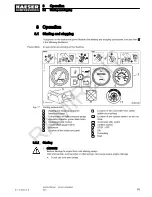
➤ The starter must not operate while the engine is running.
➤ Do not hold the start switch in the start position for longer than 30 seconds.
➤ Wait for a few minutes after each attempt to start the engine.
➤ The starter switch must be returned to the neutral position before each start attempt (re‐
start protection).
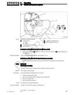
3. Turn the «Controller ON» switch
11
to the “I” position.
4. Turn the «starter switch»
12
to the “I” position.
The
charging indicator lamp
4
must light.
5. Turn the «starter switch» to “II” and hold (max. 5-10 seconds).
The engine's glow plugs are energised and the engine pre-heated.
6. Turn the «starter switch» to "III" and release it as soon as the engine starts.
The
charging indicator lamp
4
extinguishes as soon as the engine is running.
There is a fault if the charging indicator lamp does not extinguish, see chapter 9.2.
The electric fuel pump starts when the starter switch is in the "II" position. This vents the fuel
line before each start.
Maximum preheating time should be 5-10 seconds.
8.1.2 Allow the machine to run up to operating temperature
To avoid unnecessary wear, the engine should be run in IDLE until the airend discharge tempera‐
ture r30 °C. The airend discharge temperature is shown by the temperature gauge switch
on the instrument panel.
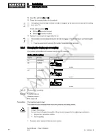
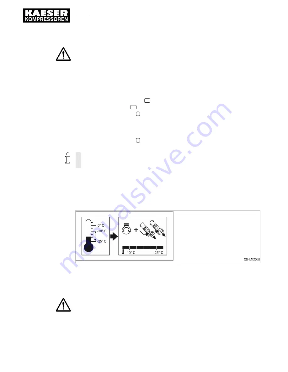
Fig. 18 Warm-up period when ambient temperatures are below -10 °C
➤ Allow the machine to warm up in IDLE (low speed).
8.1.3 Shutting down
1. CAUTION!
Thermal overload of the turbo charger.
Damage to the turbo charger by abrupt engine shutdown after high loading.
➤ Run the engine a few minutes in idle before shutting down to allow the turbo charger to
cool.
8
Operation
8.1
Starting and stopping
56
Service Manual Screw Compressor
M43
No.: 9_9432 02 E
Option ba
RAMIRENT
Содержание M43
Страница 2: ...Original instructions KKW M43 1 02 en SBA MOBILAIR PE 20100819 162014 R A M I R E N T...
Страница 8: ...List of Illustrations vi Service Manual Screw Compressor M43 No 9_9432 02 E R A M I R E N T...
Страница 220: ...13 Annex 13 3 Dimensional drawings 210 Service Manual Screw Compressor M43 No 9_9432 02 E R A M I R E N T...
Страница 222: ...13 Annex 13 3 Dimensional drawings 212 Service Manual Screw Compressor M43 No 9_9432 02 E R A M I R E N T...
Страница 224: ...13 Annex 13 3 Dimensional drawings 214 Service Manual Screw Compressor M43 No 9_9432 02 E R A M I R E N T...
Страница 226: ...13 Annex 13 3 Dimensional drawings 216 Service Manual Screw Compressor M43 No 9_9432 02 E R A M I R E N T...
Страница 228: ...13 Annex 13 4 Electrical Diagram 218 Service Manual Screw Compressor M43 No 9_9432 02 E R A M I R E N T...
Страница 229: ...13 Annex 13 4 Electrical Diagram No 9_9432 02 E Service Manual Screw Compressor M43 219 R A M I R E N T...
Страница 230: ...13 Annex 13 4 Electrical Diagram 220 Service Manual Screw Compressor M43 No 9_9432 02 E R A M I R E N T...
Страница 231: ...13 Annex 13 4 Electrical Diagram No 9_9432 02 E Service Manual Screw Compressor M43 221 R A M I R E N T...
Страница 232: ...13 Annex 13 4 Electrical Diagram 222 Service Manual Screw Compressor M43 No 9_9432 02 E R A M I R E N T...
Страница 233: ...13 Annex 13 4 Electrical Diagram No 9_9432 02 E Service Manual Screw Compressor M43 223 R A M I R E N T...
Страница 234: ...13 Annex 13 4 Electrical Diagram 224 Service Manual Screw Compressor M43 No 9_9432 02 E R A M I R E N T...
Страница 235: ...13 Annex 13 4 Electrical Diagram No 9_9432 02 E Service Manual Screw Compressor M43 225 R A M I R E N T...
Страница 236: ...13 Annex 13 4 Electrical Diagram 226 Service Manual Screw Compressor M43 No 9_9432 02 E R A M I R E N T...
Страница 244: ...13 Annex 13 6 Fuel circulation diagram 234 Service Manual Screw Compressor M43 No 9_9432 02 E R A M I R E N T...
Страница 245: ...13 Annex 13 6 Fuel circulation diagram No 9_9432 02 E Service Manual Screw Compressor M43 235 R A M I R E N T...
Страница 246: ...13 Annex 13 6 Fuel circulation diagram 236 Service Manual Screw Compressor M43 No 9_9432 02 E R A M I R E N T...

