
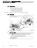


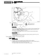


The air is then compressed in the airend
4
.
The airend is driven by an internal combustion engine.
Cooling oil is injected into the airend. It lubricates moving parts and forms a seal between the ro‐
tors themselves and between them and the airend casing. This direct cooling in the compression
chamber ensures a very low airend discharge temperature.
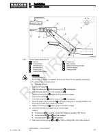
Cooling oil recovered from the compressed air in the oil separator tank
5
gives up its heat in the oil
cooler
20
. The oil then flows through the oil filter
21
and back to the point of injection. Pressure
within the machine keeps the oil circulating. A separate pump is not necessary. A thermostatic
valve
19
automatically maintains optimum cooling oil temperature.
Compressed air, freed of cooling oil in the oil separator tank
5
, flows through the minimum pres‐
sure nozzle
8
into the air air distrubutor
10
. The minimum pressure nozzle ensures that there is
always sufficient internal air pressure to maintain cooling oil circulation.
The cooling fan
28
ensures optimum cooling of all components within the enclosure.
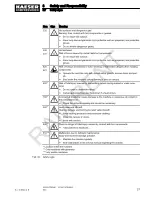
4.4 Operating modes and control modes
Item numbers correspond to the pipe and instrument flow diagram (P&ID) in chapter 13.2.
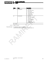
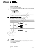
4.4.1 Operating modes
The machine operates in the following modes:
■ LOAD
─ The inlet valve is open.
─ The engine speed control cylinder is at maximum speed.
─ The airend provides compressed air for connected consumers.
─ The minimum pressure nozzle ensures that the pressure in the oil separator tank cannot fall
below the set minimum. The minimum pressure ensures continuous circulation of cooling oil
through the machine.
■ MODULATING
─ With the help of a control valve (the proportional controller) the degree of opening of the
inlet valve is steplessly varied in response to the air demand.
─ Engine speed is also varied accordingly by the control cylinder.
─ The airend provides compressed air for connected consumers.
─ This MODULATING control ensures minimum fuel consumption during times of low de‐
mand. The load and fuel consumption of the engine rises and falls with the air demand.
─ The control valve is factory set. The setting should not be changed without consultation with
KAESER SERVICE.
■ IDLE
─ The engine speed control cylinder is at minimum speed.
─ The inlet valve is closed.
─ The minimum pressure nozzle maintains minimum internal pressure.
4
Design and Function
4.4
Operating modes and control modes
28
Service Manual Screw Compressor
M43
No.: 9_9432 02 E
RAMIRENT
Содержание M43
Страница 2: ...Original instructions KKW M43 1 02 en SBA MOBILAIR PE 20100819 162014 R A M I R E N T...
Страница 8: ...List of Illustrations vi Service Manual Screw Compressor M43 No 9_9432 02 E R A M I R E N T...
Страница 220: ...13 Annex 13 3 Dimensional drawings 210 Service Manual Screw Compressor M43 No 9_9432 02 E R A M I R E N T...
Страница 222: ...13 Annex 13 3 Dimensional drawings 212 Service Manual Screw Compressor M43 No 9_9432 02 E R A M I R E N T...
Страница 224: ...13 Annex 13 3 Dimensional drawings 214 Service Manual Screw Compressor M43 No 9_9432 02 E R A M I R E N T...
Страница 226: ...13 Annex 13 3 Dimensional drawings 216 Service Manual Screw Compressor M43 No 9_9432 02 E R A M I R E N T...
Страница 228: ...13 Annex 13 4 Electrical Diagram 218 Service Manual Screw Compressor M43 No 9_9432 02 E R A M I R E N T...
Страница 229: ...13 Annex 13 4 Electrical Diagram No 9_9432 02 E Service Manual Screw Compressor M43 219 R A M I R E N T...
Страница 230: ...13 Annex 13 4 Electrical Diagram 220 Service Manual Screw Compressor M43 No 9_9432 02 E R A M I R E N T...
Страница 231: ...13 Annex 13 4 Electrical Diagram No 9_9432 02 E Service Manual Screw Compressor M43 221 R A M I R E N T...
Страница 232: ...13 Annex 13 4 Electrical Diagram 222 Service Manual Screw Compressor M43 No 9_9432 02 E R A M I R E N T...
Страница 233: ...13 Annex 13 4 Electrical Diagram No 9_9432 02 E Service Manual Screw Compressor M43 223 R A M I R E N T...
Страница 234: ...13 Annex 13 4 Electrical Diagram 224 Service Manual Screw Compressor M43 No 9_9432 02 E R A M I R E N T...
Страница 235: ...13 Annex 13 4 Electrical Diagram No 9_9432 02 E Service Manual Screw Compressor M43 225 R A M I R E N T...
Страница 236: ...13 Annex 13 4 Electrical Diagram 226 Service Manual Screw Compressor M43 No 9_9432 02 E R A M I R E N T...
Страница 244: ...13 Annex 13 6 Fuel circulation diagram 234 Service Manual Screw Compressor M43 No 9_9432 02 E R A M I R E N T...
Страница 245: ...13 Annex 13 6 Fuel circulation diagram No 9_9432 02 E Service Manual Screw Compressor M43 235 R A M I R E N T...
Страница 246: ...13 Annex 13 6 Fuel circulation diagram 236 Service Manual Screw Compressor M43 No 9_9432 02 E R A M I R E N T...


