
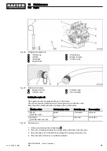
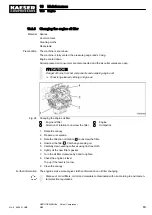
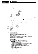


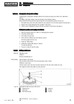
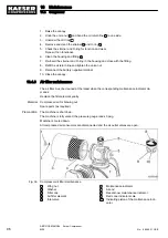
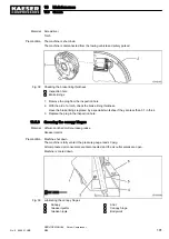

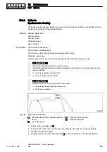

Fig. 32 Changing the cooling oil
1
Oil separator tank
2
Oil-tight plug
3
Oil separator tank drain plug
4
Oil filler
5
Oil filler plug
6
Oil cooler
7
Oil-tight plug
8
Oil cooler drain plug
9
Combination valve
10
Oil filter
Changing the cooling oil
To catch any operating fluid leaks within the machine, the floor pan is equipped with additional oil-
tight plugs at the outlet openings of the oil separator tank and oil cooler.
Both oil-tight plugs must be removed prior to draining of the cooling oil.
The oil separator tank and oil cooler drain plugs are accessible from below through openings in the
floor pan.
1. Unscrew and remove the oil-tight plugs for the oil separator tank
2
and oil cooler
7
.
2. Remove the plug
5
from the oil separator tank
1
filler.
3. Position the receptacle below the separator tank drain plug
3
.
4. Unscrew the drain plug
3
on the separator tank and allow the oil to drain into the receptacle.
5. Fit a new gasket on the drain plug
3
and screw it back in again.
6. Place the receptacle beneath the oil cooler
6
.
7. Unscrew the drain plug
8
and allow the cooling oil to drain into the receptacle.
8. Fit a new gasket on the drain plug
8
and screw it back in again.
9. Insert and tighten both oil-tight plugs.
10. Fill up the cooling oil using a funnel.
11. Check the cooling oil level.
12. Check the filler plug
4
gasket for damage.
Change a damaged gasket immediately.
13. Close the oil filler
3
using the plug
4
.
14. Reconnect the negative battery terminal.
Dispose of used oil and oil-contaminated working materials according to environmental pro‐
tection regulations.
10 Maintenance
10.4 Compressor
No.: 9_9446 01 USE
SERVICE MANUAL Screw Compressor
M26
91
Содержание M26
Страница 1: ...SERVICE MANUAL Screw Compressor M26 No 9_9446 01 USE...
Страница 187: ...13 Annex 13 2 Pipeline and instrument flow diagram P I diagram No 9_9446 01 USE SERVICE MANUAL Screw Compressor M26 179...
Страница 188: ...13 Annex 13 2 Pipeline and instrument flow diagram P I diagram 180 SERVICE MANUAL Screw Compressor M26 No 9_9446 01 USE...
Страница 189: ...13 Annex 13 2 Pipeline and instrument flow diagram P I diagram No 9_9446 01 USE SERVICE MANUAL Screw Compressor M26 181...
Страница 191: ...13 Annex 13 3 Dimensional drawing No 9_9446 01 USE SERVICE MANUAL Screw Compressor M26 183...
Страница 193: ...13 Annex 13 3 Dimensional drawing No 9_9446 01 USE SERVICE MANUAL Screw Compressor M26 185...
Страница 194: ...13 Annex 13 4 Electrical Diagram No 9_9446 01 USE SERVICE MANUAL Screw Compressor M26 187...
Страница 195: ...13 Annex 13 4 Electrical Diagram 188 SERVICE MANUAL Screw Compressor M26 No 9_9446 01 USE...
Страница 196: ...13 Annex 13 4 Electrical Diagram No 9_9446 01 USE SERVICE MANUAL Screw Compressor M26 189...
Страница 197: ...13 Annex 13 4 Electrical Diagram 190 SERVICE MANUAL Screw Compressor M26 No 9_9446 01 USE...
Страница 198: ...13 Annex 13 4 Electrical Diagram No 9_9446 01 USE SERVICE MANUAL Screw Compressor M26 191...
Страница 199: ...13 Annex 13 4 Electrical Diagram 192 SERVICE MANUAL Screw Compressor M26 No 9_9446 01 USE...
Страница 200: ...13 Annex 13 4 Electrical Diagram No 9_9446 01 USE SERVICE MANUAL Screw Compressor M26 193...
Страница 201: ...13 Annex 13 4 Electrical Diagram 194 SERVICE MANUAL Screw Compressor M26 No 9_9446 01 USE...
Страница 203: ...13 Annex 13 5 Lighting and signaling system connection 196 SERVICE MANUAL Screw Compressor M26 No 9_9446 01 USE...
Страница 204: ...13 Annex 13 5 Lighting and signaling system connection No 9_9446 01 USE SERVICE MANUAL Screw Compressor M26 197...
Страница 205: ...13 Annex 13 5 Lighting and signaling system connection 198 SERVICE MANUAL Screw Compressor M26 No 9_9446 01 USE...
Страница 206: ...13 Annex 13 5 Lighting and signaling system connection No 9_9446 01 USE SERVICE MANUAL Screw Compressor M26 199...
Страница 207: ...13 Annex 13 6 Fuel circulation diagram No 9_9446 01 USE SERVICE MANUAL Screw Compressor M26 201...
Страница 208: ...13 Annex 13 6 Fuel circulation diagram 202 SERVICE MANUAL Screw Compressor M26 No 9_9446 01 USE...