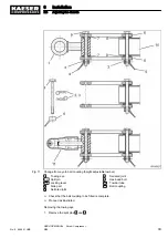
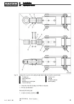
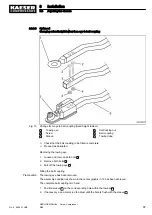


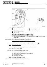
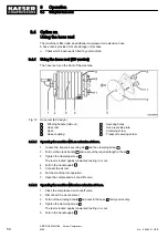
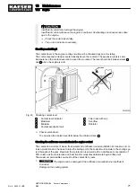

Fig. 18 Switching on the frost protector
1
Shut-off valve
A – open
B – closed
2
Control line (frost protection)
3
Frost protector
4
Control line (bypass line)
5
Oil separator tank cover
Running the machine with the frost protector (winter operation)
➤ Close the shut-off valve
1
(position B) in the frost protector control line
2
before shutting down
the compressor.
Further information Fill the frost protector with antifreeze (see chapter 10.6.2).
Running the machine without the frost protector (summer operation)
➤ Keep the shutoff valve on the frost protector permanently open (position A)
1
.
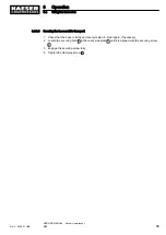
8.3.2 Coolant pre-heating
The liquid-cooled engine is equipped with an electric coolant pre-heater.
Material Power supply cable available.
Precondition The recommended pre-heating time is 2-3 hours.
1. Prepare a power supply cable.
2. Open the connection socket protective cap and hold open.
3. Plug in the supply cable.
4. Plug in the ground conductor.
Result The engine coolant will be pre-heated.
Further information Location of the connection socket, see illustration 7.
8
Operation
8.3
Using the low-temperature equipment
No.: 9_9446 01 USE
SERVICE MANUAL Screw Compressor
M26
57
Содержание M26
Страница 1: ...SERVICE MANUAL Screw Compressor M26 No 9_9446 01 USE...
Страница 187: ...13 Annex 13 2 Pipeline and instrument flow diagram P I diagram No 9_9446 01 USE SERVICE MANUAL Screw Compressor M26 179...
Страница 188: ...13 Annex 13 2 Pipeline and instrument flow diagram P I diagram 180 SERVICE MANUAL Screw Compressor M26 No 9_9446 01 USE...
Страница 189: ...13 Annex 13 2 Pipeline and instrument flow diagram P I diagram No 9_9446 01 USE SERVICE MANUAL Screw Compressor M26 181...
Страница 191: ...13 Annex 13 3 Dimensional drawing No 9_9446 01 USE SERVICE MANUAL Screw Compressor M26 183...
Страница 193: ...13 Annex 13 3 Dimensional drawing No 9_9446 01 USE SERVICE MANUAL Screw Compressor M26 185...
Страница 194: ...13 Annex 13 4 Electrical Diagram No 9_9446 01 USE SERVICE MANUAL Screw Compressor M26 187...
Страница 195: ...13 Annex 13 4 Electrical Diagram 188 SERVICE MANUAL Screw Compressor M26 No 9_9446 01 USE...
Страница 196: ...13 Annex 13 4 Electrical Diagram No 9_9446 01 USE SERVICE MANUAL Screw Compressor M26 189...
Страница 197: ...13 Annex 13 4 Electrical Diagram 190 SERVICE MANUAL Screw Compressor M26 No 9_9446 01 USE...
Страница 198: ...13 Annex 13 4 Electrical Diagram No 9_9446 01 USE SERVICE MANUAL Screw Compressor M26 191...
Страница 199: ...13 Annex 13 4 Electrical Diagram 192 SERVICE MANUAL Screw Compressor M26 No 9_9446 01 USE...
Страница 200: ...13 Annex 13 4 Electrical Diagram No 9_9446 01 USE SERVICE MANUAL Screw Compressor M26 193...
Страница 201: ...13 Annex 13 4 Electrical Diagram 194 SERVICE MANUAL Screw Compressor M26 No 9_9446 01 USE...
Страница 203: ...13 Annex 13 5 Lighting and signaling system connection 196 SERVICE MANUAL Screw Compressor M26 No 9_9446 01 USE...
Страница 204: ...13 Annex 13 5 Lighting and signaling system connection No 9_9446 01 USE SERVICE MANUAL Screw Compressor M26 197...
Страница 205: ...13 Annex 13 5 Lighting and signaling system connection 198 SERVICE MANUAL Screw Compressor M26 No 9_9446 01 USE...
Страница 206: ...13 Annex 13 5 Lighting and signaling system connection No 9_9446 01 USE SERVICE MANUAL Screw Compressor M26 199...
Страница 207: ...13 Annex 13 6 Fuel circulation diagram No 9_9446 01 USE SERVICE MANUAL Screw Compressor M26 201...
Страница 208: ...13 Annex 13 6 Fuel circulation diagram 202 SERVICE MANUAL Screw Compressor M26 No 9_9446 01 USE...