


6.3.1 Option sa
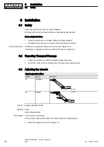
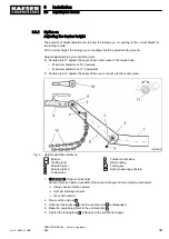
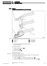
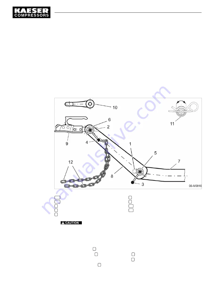
Adjusting the towbar height
The purpose of height adjustment is to bring the towing eye, or coupling, to the correct height for
the towing vehicle.
At the correct height, the towing eye or coupling should be parallel to the ground.
Height adjustment is by two serrated joints.
■ Serrated joint 1: adjusts the angle of the center piece to the towbar tube.
─ Maximum adjustment: 50° upwards.
─ Maximum adjustment: 10° downwards.
■ Serrated joint 2: adjusts the angle of the eye or coupling to the center piece.
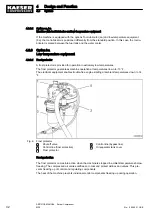
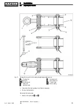
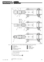
Fig. 9 Height adjustable towbar sa
1,2
Split pin
3,4
Locking lever
5
Serrated joint 1
6
Serrated joint 2
7
Towbar tube
8
Towbar center-piece
9
Ball coupling
10
Towing eye
11
Split pin securing principle
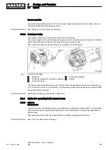
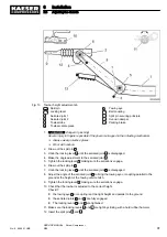
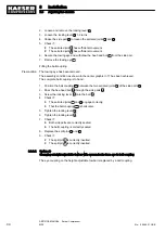
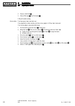
1.
Danger of pinching!
Severe injury to fingers is possible if they become trapped in the adjusting mechanism.
➤ Always wear protective gloves.
➤ Split pin retaining element
➤ Work with caution.
2. Draw out the split pin
1
.
3. Undo the locking lever
3
until the serrated joint
5
is disengaged.
4. Make the angle adjustment to the serrated joint
5
.
5. Tighten the locking lever
3
making sure the serrations engage.
6
Installation
6.3
Adjusting the chassis
No.: 9_9446 01 USE
SERVICE MANUAL Screw Compressor
M26
39
Содержание M26
Страница 1: ...SERVICE MANUAL Screw Compressor M26 No 9_9446 01 USE...
Страница 187: ...13 Annex 13 2 Pipeline and instrument flow diagram P I diagram No 9_9446 01 USE SERVICE MANUAL Screw Compressor M26 179...
Страница 188: ...13 Annex 13 2 Pipeline and instrument flow diagram P I diagram 180 SERVICE MANUAL Screw Compressor M26 No 9_9446 01 USE...
Страница 189: ...13 Annex 13 2 Pipeline and instrument flow diagram P I diagram No 9_9446 01 USE SERVICE MANUAL Screw Compressor M26 181...
Страница 191: ...13 Annex 13 3 Dimensional drawing No 9_9446 01 USE SERVICE MANUAL Screw Compressor M26 183...
Страница 193: ...13 Annex 13 3 Dimensional drawing No 9_9446 01 USE SERVICE MANUAL Screw Compressor M26 185...
Страница 194: ...13 Annex 13 4 Electrical Diagram No 9_9446 01 USE SERVICE MANUAL Screw Compressor M26 187...
Страница 195: ...13 Annex 13 4 Electrical Diagram 188 SERVICE MANUAL Screw Compressor M26 No 9_9446 01 USE...
Страница 196: ...13 Annex 13 4 Electrical Diagram No 9_9446 01 USE SERVICE MANUAL Screw Compressor M26 189...
Страница 197: ...13 Annex 13 4 Electrical Diagram 190 SERVICE MANUAL Screw Compressor M26 No 9_9446 01 USE...
Страница 198: ...13 Annex 13 4 Electrical Diagram No 9_9446 01 USE SERVICE MANUAL Screw Compressor M26 191...
Страница 199: ...13 Annex 13 4 Electrical Diagram 192 SERVICE MANUAL Screw Compressor M26 No 9_9446 01 USE...
Страница 200: ...13 Annex 13 4 Electrical Diagram No 9_9446 01 USE SERVICE MANUAL Screw Compressor M26 193...
Страница 201: ...13 Annex 13 4 Electrical Diagram 194 SERVICE MANUAL Screw Compressor M26 No 9_9446 01 USE...
Страница 203: ...13 Annex 13 5 Lighting and signaling system connection 196 SERVICE MANUAL Screw Compressor M26 No 9_9446 01 USE...
Страница 204: ...13 Annex 13 5 Lighting and signaling system connection No 9_9446 01 USE SERVICE MANUAL Screw Compressor M26 197...
Страница 205: ...13 Annex 13 5 Lighting and signaling system connection 198 SERVICE MANUAL Screw Compressor M26 No 9_9446 01 USE...
Страница 206: ...13 Annex 13 5 Lighting and signaling system connection No 9_9446 01 USE SERVICE MANUAL Screw Compressor M26 199...
Страница 207: ...13 Annex 13 6 Fuel circulation diagram No 9_9446 01 USE SERVICE MANUAL Screw Compressor M26 201...
Страница 208: ...13 Annex 13 6 Fuel circulation diagram 202 SERVICE MANUAL Screw Compressor M26 No 9_9446 01 USE...