10 Maintenance
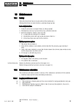
10.1 Safety
Follow the instructions below to ensure safe machine maintenance.
Warning instructions are located before a potentially dangerous task.
Basic safety instructions
1. Follow the instructions in chapter 'Safety and Responsibility'.
2. Maintenance work may only be carried out by authorized personnel.
3. Before restarting the machine, make sure that:
■ no personnel are working on the machine,
■ all protective guards and cover panels are screwed back on,
■ all tools have been removed from the machine.
Working on pressure systems
1. Disconnect all air consumers.
2. Wait until the machine is automatically vented (check that the pressure gauge indicates 0
psig).
3. Open outlet valves carefully to ensure that the line between the minimum pressure/check valve
and the compressed air outlet is vented.
4. Do not open or dismantle any valves.
Working on the drive system
1. The negative cable to the battery is disconnected.
2. The machine has cooled down.
Further information Details of authorized personnel are found in chapter 3.4.2.
Details of dangers and their avoidance are found in chapter 3.5.
10.2 Maintenance schedules
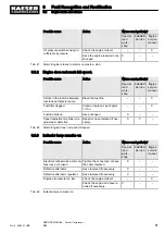
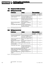
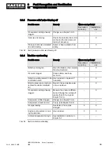
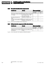
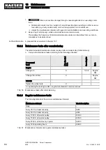
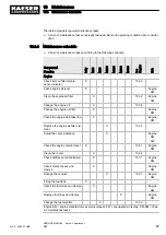
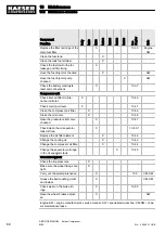
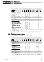
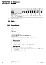
The maintenance schedules provide an overview of the maintenance instructions for the machine.
➤ Read the relative section before undertaking maintenance.
10.2.1 Logging maintenance work
The maintenance intervals given are those recommended for average applications and oper‐
ating conditions.
Maintenance schedules may be modified to take into account the application, the environ‐
ment and the quality of maintenance.
10 Maintenance
10.1 Safety
No.: 9_9446 01 USE
SERVICE MANUAL Screw Compressor
M26
65
Содержание M26
Страница 1: ...SERVICE MANUAL Screw Compressor M26 No 9_9446 01 USE...
Страница 187: ...13 Annex 13 2 Pipeline and instrument flow diagram P I diagram No 9_9446 01 USE SERVICE MANUAL Screw Compressor M26 179...
Страница 188: ...13 Annex 13 2 Pipeline and instrument flow diagram P I diagram 180 SERVICE MANUAL Screw Compressor M26 No 9_9446 01 USE...
Страница 189: ...13 Annex 13 2 Pipeline and instrument flow diagram P I diagram No 9_9446 01 USE SERVICE MANUAL Screw Compressor M26 181...
Страница 191: ...13 Annex 13 3 Dimensional drawing No 9_9446 01 USE SERVICE MANUAL Screw Compressor M26 183...
Страница 193: ...13 Annex 13 3 Dimensional drawing No 9_9446 01 USE SERVICE MANUAL Screw Compressor M26 185...
Страница 194: ...13 Annex 13 4 Electrical Diagram No 9_9446 01 USE SERVICE MANUAL Screw Compressor M26 187...
Страница 195: ...13 Annex 13 4 Electrical Diagram 188 SERVICE MANUAL Screw Compressor M26 No 9_9446 01 USE...
Страница 196: ...13 Annex 13 4 Electrical Diagram No 9_9446 01 USE SERVICE MANUAL Screw Compressor M26 189...
Страница 197: ...13 Annex 13 4 Electrical Diagram 190 SERVICE MANUAL Screw Compressor M26 No 9_9446 01 USE...
Страница 198: ...13 Annex 13 4 Electrical Diagram No 9_9446 01 USE SERVICE MANUAL Screw Compressor M26 191...
Страница 199: ...13 Annex 13 4 Electrical Diagram 192 SERVICE MANUAL Screw Compressor M26 No 9_9446 01 USE...
Страница 200: ...13 Annex 13 4 Electrical Diagram No 9_9446 01 USE SERVICE MANUAL Screw Compressor M26 193...
Страница 201: ...13 Annex 13 4 Electrical Diagram 194 SERVICE MANUAL Screw Compressor M26 No 9_9446 01 USE...
Страница 203: ...13 Annex 13 5 Lighting and signaling system connection 196 SERVICE MANUAL Screw Compressor M26 No 9_9446 01 USE...
Страница 204: ...13 Annex 13 5 Lighting and signaling system connection No 9_9446 01 USE SERVICE MANUAL Screw Compressor M26 197...
Страница 205: ...13 Annex 13 5 Lighting and signaling system connection 198 SERVICE MANUAL Screw Compressor M26 No 9_9446 01 USE...
Страница 206: ...13 Annex 13 5 Lighting and signaling system connection No 9_9446 01 USE SERVICE MANUAL Screw Compressor M26 199...
Страница 207: ...13 Annex 13 6 Fuel circulation diagram No 9_9446 01 USE SERVICE MANUAL Screw Compressor M26 201...
Страница 208: ...13 Annex 13 6 Fuel circulation diagram 202 SERVICE MANUAL Screw Compressor M26 No 9_9446 01 USE...

