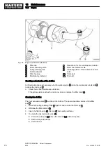
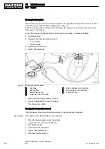

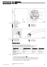
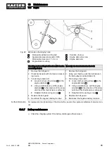
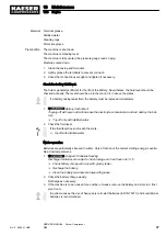
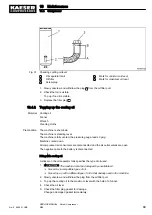


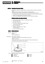
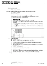

Fig. 29 Belt tension checking by hand
A
Permissible deflection of the belt
*
Approximate pressure exerted: 50 lb
Permissible movement: 7 – 9 mm
1
Engine block mounting
2
Direction of arrow
3
Engine alternator screw
4
Engine alternator
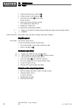
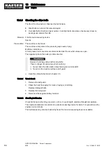
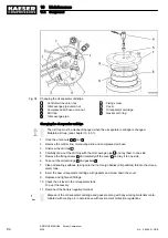
Checking and resetting belt tension with tension
measuring device:
Manually check and retension the belt:
1. Remove the belt guard.
2. Check belt tension with the tension measur‐
ing device.
3. Tensioning a loose belt:
■ Loosen both securing screws
3
on the
engine alternator
4
.
■ Using a suitable lever, pull the engine
alternator
2
in the direction of the arrow
until the correct belt tension is achieved.
■ Retighten both securing screws
3
.
4. Replace the belt guard.
5. Reconnect the negative battery terminal.
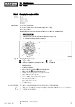
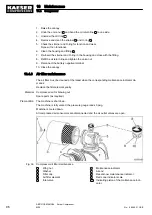
1. Remove the belt guard.
2. Using your thumbs, push the belt between
the belt pulleys (see illustration 29).
3. Tensioning a loose belt:
■ Loosen both securing screws
3
on the
engine alternator
4
.
■ Using a suitable lever, pull the engine
alternator
2
in the direction of the arrow
until the correct belt tension is achieved.
■ Retighten both securing screws
3
.
4. Replace the belt guard.
5. Reconnect the negative battery terminal.
Further information For replacement and tensioning of the drive belts, see also the engine manufacturer's service man‐
ual.
10.3.7 Battery maintenance
➤ Check the charging system if the battery discharges without reason.
10 Maintenance
10.3 Engine
No.: 9_9446 01 USE
SERVICE MANUAL Screw Compressor
M26
85
Содержание M26
Страница 1: ...SERVICE MANUAL Screw Compressor M26 No 9_9446 01 USE...
Страница 187: ...13 Annex 13 2 Pipeline and instrument flow diagram P I diagram No 9_9446 01 USE SERVICE MANUAL Screw Compressor M26 179...
Страница 188: ...13 Annex 13 2 Pipeline and instrument flow diagram P I diagram 180 SERVICE MANUAL Screw Compressor M26 No 9_9446 01 USE...
Страница 189: ...13 Annex 13 2 Pipeline and instrument flow diagram P I diagram No 9_9446 01 USE SERVICE MANUAL Screw Compressor M26 181...
Страница 191: ...13 Annex 13 3 Dimensional drawing No 9_9446 01 USE SERVICE MANUAL Screw Compressor M26 183...
Страница 193: ...13 Annex 13 3 Dimensional drawing No 9_9446 01 USE SERVICE MANUAL Screw Compressor M26 185...
Страница 194: ...13 Annex 13 4 Electrical Diagram No 9_9446 01 USE SERVICE MANUAL Screw Compressor M26 187...
Страница 195: ...13 Annex 13 4 Electrical Diagram 188 SERVICE MANUAL Screw Compressor M26 No 9_9446 01 USE...
Страница 196: ...13 Annex 13 4 Electrical Diagram No 9_9446 01 USE SERVICE MANUAL Screw Compressor M26 189...
Страница 197: ...13 Annex 13 4 Electrical Diagram 190 SERVICE MANUAL Screw Compressor M26 No 9_9446 01 USE...
Страница 198: ...13 Annex 13 4 Electrical Diagram No 9_9446 01 USE SERVICE MANUAL Screw Compressor M26 191...
Страница 199: ...13 Annex 13 4 Electrical Diagram 192 SERVICE MANUAL Screw Compressor M26 No 9_9446 01 USE...
Страница 200: ...13 Annex 13 4 Electrical Diagram No 9_9446 01 USE SERVICE MANUAL Screw Compressor M26 193...
Страница 201: ...13 Annex 13 4 Electrical Diagram 194 SERVICE MANUAL Screw Compressor M26 No 9_9446 01 USE...
Страница 203: ...13 Annex 13 5 Lighting and signaling system connection 196 SERVICE MANUAL Screw Compressor M26 No 9_9446 01 USE...
Страница 204: ...13 Annex 13 5 Lighting and signaling system connection No 9_9446 01 USE SERVICE MANUAL Screw Compressor M26 197...
Страница 205: ...13 Annex 13 5 Lighting and signaling system connection 198 SERVICE MANUAL Screw Compressor M26 No 9_9446 01 USE...
Страница 206: ...13 Annex 13 5 Lighting and signaling system connection No 9_9446 01 USE SERVICE MANUAL Screw Compressor M26 199...
Страница 207: ...13 Annex 13 6 Fuel circulation diagram No 9_9446 01 USE SERVICE MANUAL Screw Compressor M26 201...
Страница 208: ...13 Annex 13 6 Fuel circulation diagram 202 SERVICE MANUAL Screw Compressor M26 No 9_9446 01 USE...