


(No.YA318)1-51
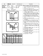
4.6.5 MTS ADJUSTMENT
Item
Measuring
instrument
Test point
Adjustment part
Description
MTS INPUT
LEVEL
Remote
control unit
[1.PICTURE/SOUND]
A01: IN LEVEL
(1) Receive the any broadcast.
(2) Select the 1.PICTURE/SOUND from the SERVICE
MODE.
(3) Select the < A01 > (IN LEVEL).
(4) Set the intal setting value of the < A01 >.
(5) Press the [MUTING] key to memorize the set value.
MTS
SEPARATION
TV audio
multiplex
signal
generator
Oscilloscope
Remote
control unit
R OUT
L OUT
[AUDIO OUT]
[1.PICTURE/SOUND]
A02: LOW SEP
A03: HI SEP
(1) Input the stereo L signal (300Hz) from the TV audio
multiplex signal generator to the antenna terminal.
(2) Connect an oscilloscope to L OUT pin of the AUDIO
OUT, and display one cycle portion of the 300Hz
signal.
(3) Change the connection of the oscilloscope to R OUT
pin of the AUDIO OUT, and enlarge the voltage axis.
(4) Select 1.PICTURE/SOUND from the SERVICE
MODE.
(5) Select the < A02 > (LOW SEP).
(6) Set the initial setting value of the < A02 > (LOW
SEP).
(7) Adjust the < A02 > so that the stroke element of the
300Hz signal will become minimum.
(8) Select the < A03 > (HI SEP).
(9) Change the signal to 3kHz, and similarly adjust the
< A03 > (HI SEP).
(10) Press the [MUTING] key to memorize the set value.
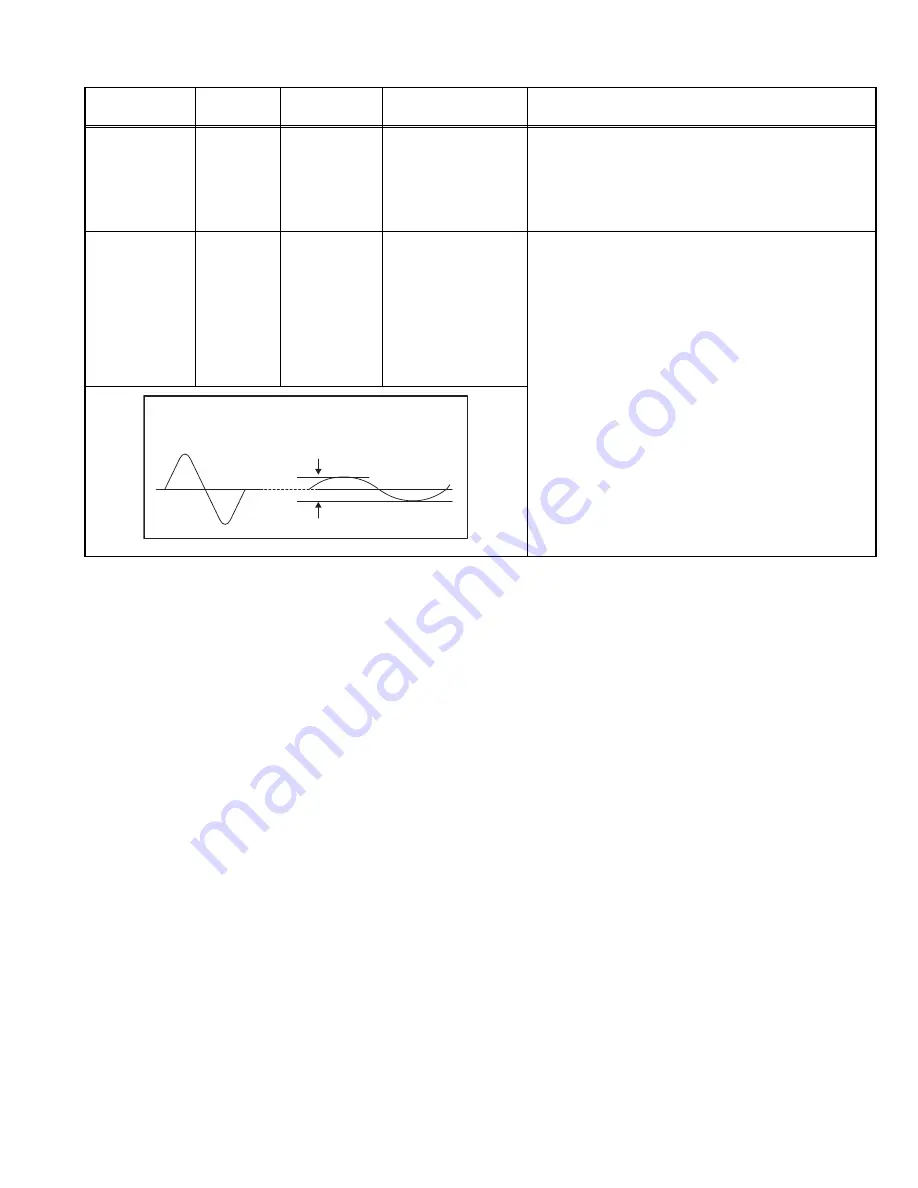
L-Channel
signal waveform
R-Channel
crosstalk portion
Minimum
1 cycle
Содержание AV-48P776/H
Страница 1: ......
Страница 92: ... No YA318 2 4 ...
Страница 135: ...2 47 No YA318 PATTERN DIAGRAMS MAIN PWB PATTERN SOLDER SIDE ...
Страница 136: ... No YA318 2 48 FRONT ...
Страница 137: ...2 49 No YA318 MAIN PWB PATTERN PARTS SIDE ...
Страница 138: ... No YA318 2 50 FRONT ...