


(No.YA318)1-13
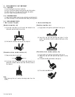
3.1.12 REMOVING THE MAIN UNIT (Fig.3)
• Remove the SPEAKER GRILL.
• Remove the FRONT PANEL.
• Remove the FRONTCONTROL BOX.
• Remove the REAR PANEL.
(1) Remove 4 screws [N] from front side of both sides.
(2) Remove 2 screws [O] attaching the MAIN CHASSIS and
BODY.
(3) Remove the SPEAKER CONNECTOR.
(4) Pull out the MAIN UNIT rear side.
NOTE :
• Except for confirmation of projection of images on the screen
and audio output through the speakers, the removed MAIN
UNIT is still workable in the same state as if it is still built-in
the TV set. Therefore, the MAIN UNIT can be removed, if
necessary, for board diagnosis, electric testing, etc. apart
from confirmation of screen images and audio output.
• When wire clamps are removed during work, use care to
restore them precisely to their original positions.
Performance can be affected if these are not returned to the
original positions.
• Because of the large size, at least 2 persons are
recommended for removal and reassemble.
• When carrying the MAIN UNIT, use care not to drop, shock
or shake it.
• Do not stain or damage the lens of the PROJECTION UNIT.
• Do not look the projection side of a PROJECTION UNIT
when the image is projected.
3.1.12.1 CHECKING THE P.W. BOARD (Fig.2)
When checking the MAIN PWB, POWER PWB, DEF &
CONVERGENCE OUT PWB, etc., raise the MAIN UNIT with the
front side down for the make of convenience.
3.1.12.2 REMOVING THE FOCUS PACK (Fig.2)
• Remove the MAIN UNIT.
(1) Remove 1 screw
[P]
.
(2) Remove the FOCUS PACK.
(3) Remove wires connecting the FOCUS PACK.
3.1.13 REMOVING THE AV TERMINAL BOARD (Fig.2)
• Remove the REAR PANEL.
(1) Remove 1 screws
[Q]
.
(2) Remove 5 screws
[R]
.
(3) Pull out the POWER CORD CLAMP from AV TERMINAL
BOARD right side.
(4) Remove the AV TERMINAL BOARD.
3.1.13.1 REMOVING THE SD CARD PWB (Fig.2)
• Remove the REAR PANEL.
• Remove the AV TERMINAL BOARD.
(1) Remove 2 screws
[S]
.
(2) Remove the SD CARD PWB.
3.1.14 REMOVING THE MAIN CHASSIS (Fig.2)
• Remove the REAR PANEL.
(1) Remove 2 screws
[T]
.
(2) Pull out the MAIN CHASSIS for backside.
NOTE :
• If necessary, remove the anode wires, connectors,
respectively.
3.1.15 REMOVING THE DIGITAL SIGNAL PWB (Fig.2)
• Remove the REAR PANEL.
• Remove the AV TERMINAL BOARD.
• Remove the MAIN CHASSIS.
(1) Remove the craw
[U]
on the
CN1004
connector.
(2) Remove the DIGITAL SIGNAL PWB.
3.1.15.1 REMOVING THE ATSC TUNER MODULE PWB
(Fig.2)
• Remove the REAR PANEL.
• Remove the AV TERMINAL BOARD.
• Remove the MAIN CHASSIS.
(1) Remove 2 screws
[V]
.
(2) Pull out the ATSC TUNER MODULE PWB.
3.1.15.2 REMOVING THE DIGITAL CONVERGENCE
• Remove the REAR PANEL.
• Remove the AV TERMINAL BOARD.
• Remove the MAIN CHASSIS.
(1) Remove 2 screws
[W]
.
(2) Pull out the DIGITAL CONVERGENCE MODULE PWB.
3.1.15.3 REMOVING THE DEF & CONVERGENCE OUT PWB
(Fig.2)
• Remove the REAR PANEL.
• Remove the MAIN CHASSIS.
(1) Remove 1 screw
[X]
.
(2) Remove the DEF & CONVERGENCE OUT PWB.
3.1.16 REMOVING THE POWER PWB (Fig.2)
• Remove the REAR PANEL.
• Remove the MAIN CHASSIS.
(1) Remove 1 screw
[Y]
.
(2) Remove the POWER PWB.
Содержание AV-48P776/H
Страница 1: ......
Страница 92: ... No YA318 2 4 ...
Страница 135: ...2 47 No YA318 PATTERN DIAGRAMS MAIN PWB PATTERN SOLDER SIDE ...
Страница 136: ... No YA318 2 48 FRONT ...
Страница 137: ...2 49 No YA318 MAIN PWB PATTERN PARTS SIDE ...
Страница 138: ... No YA318 2 50 FRONT ...