


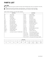

1-44 (No.YA318)
OVERALL
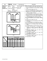
CONVERGENCE
(POINT)
adjustment
Signal
generator
Remote
control unit
[ 7.CONVER B ]
NOTE:
Perform this adjustment after performing OVERALL
CONVERGENCE (LINE) check.
It adjusts displaying and checking adjustment data by
the [DISPLAY] key. Adjust in order of area A, area B,
area C and area D.
(1) Receive NTSC crosshatch signal.
(2) Select 7.CONVER B from SERVICE MENU. Then
appear green crosshatch pattern for adjustment.
(See Fig.1)
(3) Press [DISPLAY] key for displaying and checking
adjustment data.
(4) Press [ 2 ] / [ 4 ] / [ 5 ] / [ 6 ] / [ 8 ] keys respectively,
move the cursor to the adjusting point.
(5) Press [CH+] / [CH-] / [VOL+] / [VOL-] keys, adjust the
position of the adjusting point so that it is located at
the place as shown in Fig.2.
(6) Adjust area A.
(7) Adjust area B.
(8) Adjust area C.
(9) Adjust area D. It adjusts toward an outside from the
inside of a screen. (e.g. H#3 > H#2 > ---)
H#0 is fixed data with the value inputted by
adjustment of area C. When the point of H#0 needs
to be adjusted, adjusts the data of H#1 and H#2.
If the data of H#1 adjusts H#0, H#2 will move, the
data of H#2 adjusts H#1 and H#2. It repeats if
needed. (See Fig.3)
(10) Press [SLEEP TIMER] key to select the red and blue
crosshatch patterns, respectively, and make
convergence adjustments so that they align with the
adjusting points of the green crosshatch pattern
(reference color).
(11) Press [OK] key to change the display colors to 3
colors from 2 colors (adjusting color + green) and
make sure that the convergence has been aligned
with each other.
(12) Press [MUTING] key to memorize the set values.
(13) Perform an AUTO CONVERGENCE PRESET.
Fig.3
Fig.1
Fig.2
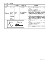
Item
Measuring
instrument
Test point
Adjustment part
Description
H#0H#1
ADJUSTMENT PROCEDURE OF LINE H#1
NOTE:
Adjust in consideration of a surrounding line moving.
H#2
H#0H#1
H#2
H#0H#1
H#2
Cursor
Point of adjustment
A1
A2
A3
A4
B1
B2
B3
B4
H#4
H#3
H#2
H#0
V#0
V#1
V#2
V#3
V#4
V#5
V#6
V#7
V#8
H#1
H#5
H#6
H#8
H#7
: 0 V#4 :
: 0 V#4 :
#4 : 0 V#4 : 0
H
H#
#
#
Area A
Area B
Area D
Area C
56" model
204
A1
SPAN TABLE (mm)
48" model
174
407
A2
348
509
A3
435
611
A4
522
96
B1
82
192
B2
164
287
B3
246
335
B3
287
Содержание AV-48P776/H
Страница 1: ......
Страница 92: ... No YA318 2 4 ...
Страница 135: ...2 47 No YA318 PATTERN DIAGRAMS MAIN PWB PATTERN SOLDER SIDE ...
Страница 136: ... No YA318 2 48 FRONT ...
Страница 137: ...2 49 No YA318 MAIN PWB PATTERN PARTS SIDE ...
Страница 138: ... No YA318 2 50 FRONT ...