


1-14 (No.YA318)
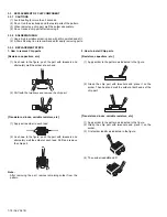
3.1.16.1 REMOVING THE PROJECTION UNIT (Fig.2)
• Remove the SPEAKER GRILL.
• Remove the FRONT PANEL.
• Remove the FRONT CONTROL BOX.
• Remove the REAR PANEL.
• Remove the MAIN UNIT.
(1) Remove the CRT SOCKET PWB.
(2) Remove 4 screws
[Z]
.
(3) Pull out the PROJECTION UNIT upward.
NOTE :
• Refer to "PROJECTION UNIT REPLACEMENT" when
taking out and replacing the PROJECTION UNIT.
• When wire clamps are removed during work, use care to
restore them precisely to their original positions.
Performance can be affected if these are not returned to the
original positions.
3.1.16.2 REMOVING THE HV DIVIDER (Fig.2)
• Remove the REAR PANEL.
(1) Remove 1 screw
[a]
.
(2) Remove the HV DIVIDER.
NOTE :
• Wires of the transformer (FBT) and CRT of each
PROJECTION UNIT can be removed by turning the connector
portions.
• If necessary, remove the anode wires, and replacing the HV
DIVIDER, take care to correctly engage the connector.
3.1.16.3 REMOVING THE REMOTE SENSOR PWB (Fig.2)
• Remove the REAR PANEL.
(1) Remove 1 screw
[b]
.
(2) Remove the REMOTE SENSOR PWB.
3.1.16.4 REMOVING THE COOLANT PAN (Fig.2)
• Remove the REAR PANEL.
(1) Remove 2 screw
[c]
.
(2) Remove the COOLANT PAN.
Содержание AV-48P776/H
Страница 1: ......
Страница 92: ... No YA318 2 4 ...
Страница 135: ...2 47 No YA318 PATTERN DIAGRAMS MAIN PWB PATTERN SOLDER SIDE ...
Страница 136: ... No YA318 2 48 FRONT ...
Страница 137: ...2 49 No YA318 MAIN PWB PATTERN PARTS SIDE ...
Страница 138: ... No YA318 2 50 FRONT ...