


(No.YA318)1-9
2.7
PROJECTION UNIT REPLACEMENT
2.7.1 ADJUSTMENT DURING REPLACEMENT
When replacing the three R, G and B projection units, first replace the R and B units and perform focus / screen / raster centering
adjustments with reference to the G unit. Then replace the G unit and perform G focus / screen / convergence adjustment. Finally
perform R & B . Convergence adjustments. Use care to simultaneously removes all three-projection units.
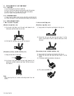
2.7.2 DISASSEMBLY CAUTION
The projection units include locations that are not to be disassembled during service. When replacing projection unit parts,
disassemble to the state indicated in the figure below.
The figure indicates screws and wires that are not to be removed. Use care not to remove these.
LENS ASS'Y SCREW ( x 4)
LENS ASS'Y
CRT ASS'Y (COUPLER ASS'Y)
DEF. / CONVER. YOKE
VM PWB (G only)
TAPE
2/4 POLE
MAGNET
R CRT SOCKET PWB ASS'Y
G CRT SOCKET PWB ASS'Y
B CRT SOCKET PWB ASS'Y
Check that tape is applied to the CRT neck.
If absent, the deflection yoke can dislodge.
Deflection yoke wires : to connector on DEF/CONVERGENCE OUT PWB ASS'Y.
[R="RHV", G="GHV", B="BHV"]
Convergence yoke wires : to connector on DEF/CONVERGENCE OUT PWB ASS'Y.
[R="R", G="G", B="B"]
Do not remove screws
Do not disassembly
ANODE wires : to DIVIDER
Содержание AV-48P776/H
Страница 1: ......
Страница 92: ... No YA318 2 4 ...
Страница 135: ...2 47 No YA318 PATTERN DIAGRAMS MAIN PWB PATTERN SOLDER SIDE ...
Страница 136: ... No YA318 2 48 FRONT ...
Страница 137: ...2 49 No YA318 MAIN PWB PATTERN PARTS SIDE ...
Страница 138: ... No YA318 2 50 FRONT ...