


REV
. 10
22-04-2020
INSTALLATION
,
USE AND MAINTENANCE MANUAL
–
PN
14 / 40
Jurop
SpA
Via Crosera n° 50
33082 Azzano Decimo, PN (Italia)
T
EL
. +39 0434 636811 F
AX
. +39 0434 636812
http://www.jurop.it
e-mail: [email protected]
DRAINING
PORT
C) Hydraulic drive transmission
Model
Displacement
Operating pressure
(max. vac.)
Operating pressure
(1 rel. bar)
Flow at Max Speed
Max pressure
draining line
Max. pressure
motor exhaust
Max pressure
PN 23
19 cc/rev
100 bar
130 bar
26 l/min (1300rpm)
-
5 bar
250 bar
PN 33
19 cc/rev
160 bar
200 bar
26 l/min (1300rpm)
-
5 bar
250 bar
PN 45
34.5 cc/rev
110 bar
140 bar
46 l/min (1300rpm)
5 bar
5 bar
230 bar
PN 58
44 cc/rev
110 bar
140 bar
59 l/min (1350rpm)
5 bar
5 bar
220 bar
PN 84
61 cc/rev
120 bar
150 bar
84 l/min (1300rpm)
5 bar
5 bar
170 bar
PN 106
72 cc/rev
120 bar
160 bar
98 l/min (1200rpm)
5 bar
5 bar
230 bar
(*) : Oil temperature, used in the main circuit.
•
Fluid
: mineral oil for hydraulic systems in compliance with
ISO/DIN.
Temperature
Optimum viscosity ale
Max. viscosity allowed
-20 / +80 °C
12 – 100 cSt
750 cSt
•
Filtration
: class 21/19/16 contamination according to ISO 4406 to
be obtained with a ßx = 75 filter.
•
Check circuit connections
: they must be applied in the same
rotation direction as that indicated by the arrow on the pump front
flange.
•
Draining
: connect directly to the tank above the maximum oil
level. Operating without draining line may damage the motor.
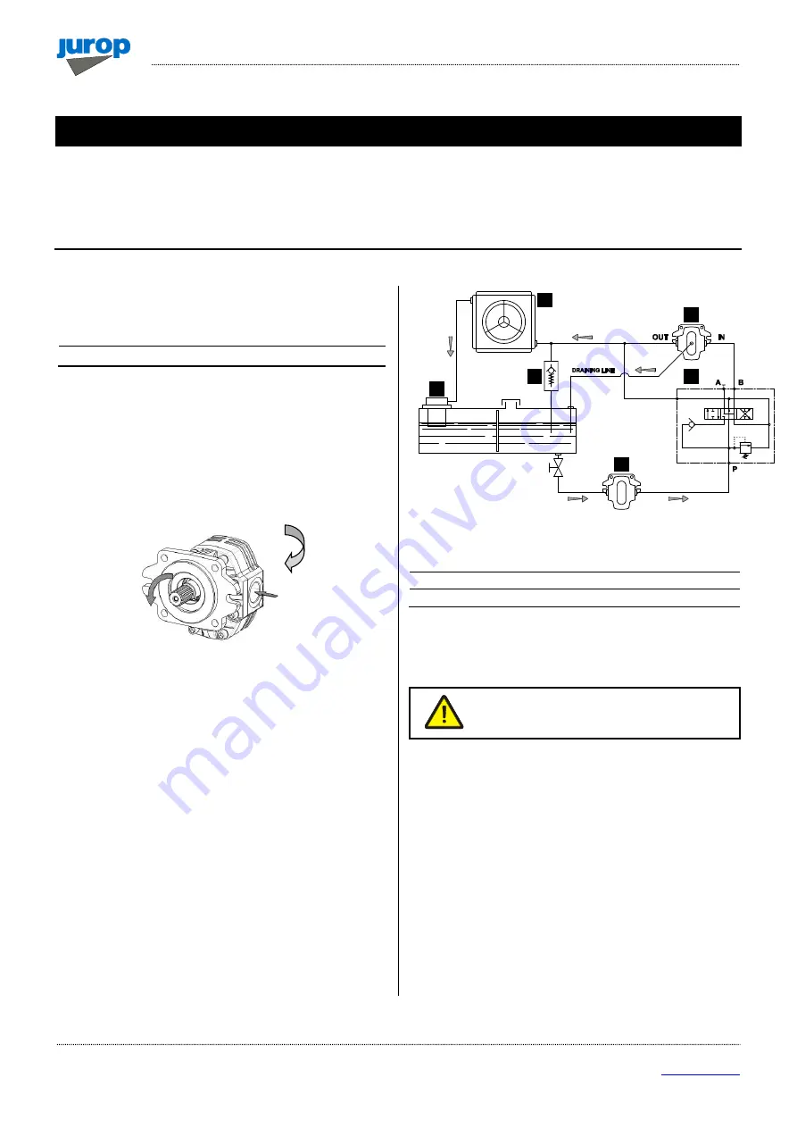
Pic. 4.6
•
Distributor
: open-centre distributor in central idle position
(vacuum pump off). It must be equipped with an adjustable
overpressure safety valve.
•
Motor pipeline
: outlet pipe must not be of a smaller diameter than
that of the inlet port. Inlet pipes always have a diameter smaller than
outlet pipes. Choose preferably flexible pipes to avoid vibration
transmission.
• Tank
: with suction pipe and return separated by baffles. If
necessary, use a heat exchanger to avoid oil heating above 70-80°C
and protect it from extreme pressure with a pressure relief valve.
Minimum approximate capacity: as twice as the circulation flow.
•
Starting-up
: be sure that the system is well cleaned and pour oil
into the tank and into the motor housing (necessary to lubricate the
internal bearings).
• Vent the circuit and adjust the overpressure safety valve to the
lowest possible value.
• Check the oil tank level.
• Increase pressure and rotation speed until operating values are
reached.
Pic. 4.7
1
HYD Pump
4
Oil Filter
2
Distributor
5 *
Heat exchanger
3
HYD Motor
6 *
Safety valve
* optional components
• The machine/system manufacturer is responsible for dimensioning
the lines.
The machine/system manufacturer is responsible
for dimensioning the lines.
4
6
3
5
2
1