


REV
. 10
22-04-2020
INSTALLATION
,
USE AND MAINTENANCE MANUAL
–
PN
12 / 40
Jurop
SpA
Via Crosera n° 50
33082 Azzano Decimo, PN (Italia)
T
EL
. +39 0434 636811 F
AX
. +39 0434 636812
http://www.jurop.it
e-mail: [email protected]
• Vacuum control valve has to be fitted on the suction piping, if the
tank's characteristics or the vacuum line will need this kind of vacuum-
limiting device.
• In the event of pressurised operation, the rotation of the 4-way
diverter valve enables suction from the silencer and air to be sent into
the system. Check the rotation capacity so as not to generate
excessive pressure in delivery.
• In the event of overheating, the opening of the safety gate valve
applied on the suction inlet does not cool the pump working under
pressure. Stop transmission.
• The valve at the decompressor suction inlet avoids rotation when it
is stopped under load, but the circuit must be bled:
Before servicing the decompressor or transmission. The
pressure difference inside the system can make the machine
run;
Before restarting the machine: it requires high starting torque.
Attention: if the decompressor is stopped under
load, bleed the circuit before any maintenance
operations.
• An adjustable curved pipe is installed on the outlet of the silencer,
in order to prevent rain from entering and to enable positioning (during
installation) of the output airflow.
• Direct the silencer discharge outlet away from the silencer suction
inlet in order to prevent the input of hot fluids into the injection inlet.
Direct the silencer discharge outlet away from the
silencer suction inlet in order to prevent the input
of hot fluids into the injection inlet.
• An oil-separator must be installed in correspondence of the
discharge line of PN. Besides reducing the noise produced by the air
flow along the vacuum line, the silencer also traps the oil vapor at the
outlet due to decompressor lubrication.
4.7
Vacuum-pressure
inverter:
remote
control
actuators
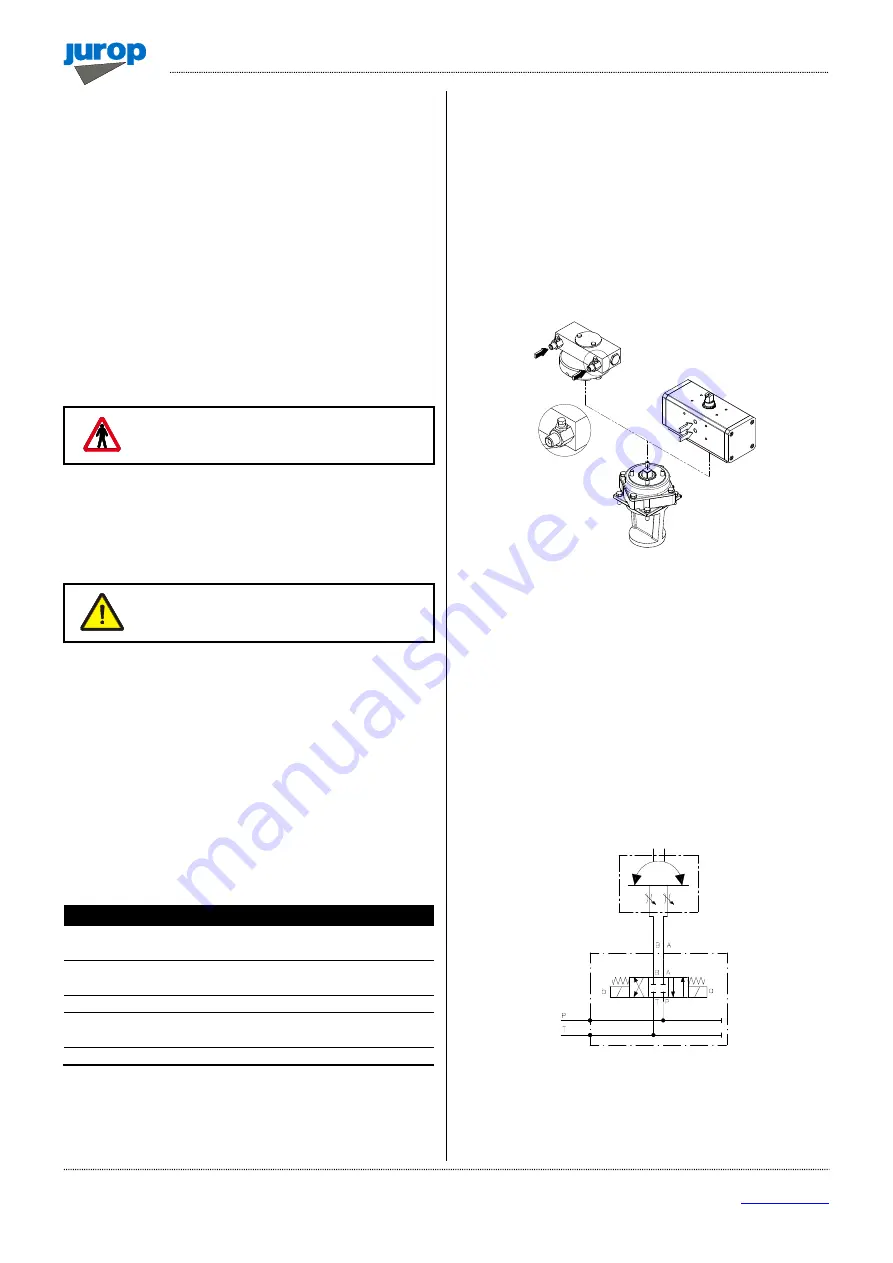
• A specific design of the vacuum-pressure diverter available on
request enables the application of a pneumatic or hydraulic angular
actuator (90°).
• See the exploded view at the end of the manual for spare parts.
Pneumatic actuator
Hydraulic actuator
Fluid
Filtered, dried
compressed air
Hydraulic oil
ISO-L-HM
Filtration
ISO 8573-1 classe 4
(15 micron)
ISO 4406 21/19/16
Temperature
-20 ÷ +80 °C
-20 ÷ +80 °C
Rated pressure
5.6 bar
150 bar
Maximum pressure
8.4 bar
200 bar
Supply holes
G 1/4
G 1/8
Hydraulic actuator installation
• Adjust movement speed using the two built-in valves.
• Use a closed-center distributor or apply a block valve.
Pneumatic actuator installation
• Adjust movement speed by applying two unidirectional flow control
valves.
For both actuators
• Adjust speed: full rotation should not take less than 1 second.
• Fluid filtration: ensure a level equal to or greater than the
recommended value.
• In the event of a (hydraulic or pneumatic) supply failure, the
suction unit inverter will remain in the same position it was when the
failure occurred.
Pic. 4.3
Maintenance
• The diverter is adjusted before shipment and does not usually
require further adjustments.
• Diverter lubrication:
-
Use Lithium grease NLGI 2. Quantity: 80-100 g every 1000
working cycles.
-
Do not grease using excessive amounts of grease.
• Hydraulic actuator: the control valves are equipped with an internal
metal filter. Disassemble and clean if movement stops.
• Pneumatic actuator: for non-dried air, use temperature 0 ÷ +80°C.
• The following figure shows a possible schematic view of a correct
hydraulic connection.
• The following figure shows a possible schematic view of a
pneumatic connection.
HYDRAULIC ACTUATOR
SPEED ADJUSTMENT