jurop PN 106 Скачать руководство пользователя страница 10

REV

. 10

22-04-2020

INSTALLATION

,

USE AND MAINTENANCE MANUAL

PN

10 / 40

Jurop

SpA

Via Crosera n° 50
33082 Azzano Decimo, PN (Italia)

T

EL

. +39 0434 636811 F

AX

. +39 0434 636812

http://www.jurop.it

e-mail: [email protected]
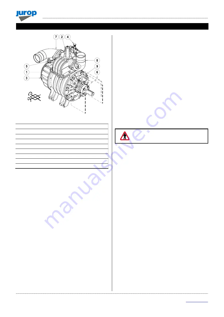
Pic. 4.1

Main components legend

1.

Manifold with built-in check valve

2.

Vacuum/Pressure change-over valve

3.

Rear oil tank with lubrication pump

4.

Drip oilers

5.

Oil filling port and dip stick

6.

Shaft protection

7.

Swivelling conveyor

8.

Conveyor with safety valve connection

9.

Front bearing lubrication

4.1.

Compulsory accessories

• Compulsory accessories for a correct running of the pump:

Safety filter mounted between the pump and the secondary
shutoff.

Over-pressure safety relief valve.

4.2.

Checking upon receipt

• When the goods are delivered, make sure that all parts listed on

the delivery note are in perfect condition and have suffered no damage
during shipping.

• Remove the parts of the packaging that can be dangerous if

sucked by the compressor.

• Make sure the vacuum pump has its identification plate. Pumps

without such identification are to be considered anonymous and
potentially dangerous: in such an event, they must not be used,
otherwise the manufacturer will be deemed free from any liability
whatsoever.

4.3.

Storing in the warehouse

• If the pump will not be installed inside a short time after delivery:

Store in a closed and dry place.

Remove the guards from the ports and spray a film of
protective oil over the inner surfaces of the body, rotors and
sides. Then attach again the guards.

Renew the preserving oil periodically.

• To temporarily store a used pump, follow the instructions below:

Thoroughly clean the pump.

Equip the pump with suitable anti-corrosion protection.

4.4.

Handling and installation

• Before each movement, verify that the lifting equipment has a

suitable capacity (check the weight of the pump, possibly showed in
this manual, in the paragraph 2.2).

• Do not lift the packaging or the machine when moving more than

50 cm from the ground. Proceed with the final lifting only near the
installation point.

• Harness the machine with suitable straps / chains near the main

body, paying attention to the position of the mass centre of gravity to
ensure the load stability.

Warning: do not stand under the machine when it
is lifted during the installation.

4.5.

Mounting

• The pump must be assembled for an easy access for maintenance

operations and secured rigidly to a frame or levelled base (max. 3°
slant to the horizontal plane. See Fig. 4.1). The base must be such as
to avoid vibrations, bending or deformation.

• It is recommended to install the pump on vibration adsorbing pads

to reduce the noise and vibrations produced during its operation.

• Leave enough space around the pump to allow the free circulation

of air for cooling; avoid exposure to dirt and debris.

• Provide the necessary space to reach all points of lubrication

control (oil level), and the oil tank filler cap, the lever of the 4-way
switch, vanes inspection ports. See Pic. 4.1.

• The oil tank is mounted on the rear side of the pump. Instead for

PN 106 the oil tank is mounted on the suction side of the housing.

• Provide for suitable manoeuvring spaces of the inverter lever. The

control lever has two possible switching positions well defined by the
latches and numbers reported on the fusion. It is directly connected to
the internal diverter tang of the inverter, making it very intuitive: 90° of
the lever switching corresponds to 90° of the inverter switching.

• Based on the functionality of the system which will house the

decompressor, the designer of the end machine, must:

Properly signal the functionality of the inverter according to the
position of the manual operating lever or of the pneumatic
actuator or of the hydraulic one.

Install suitable pressure and / or vacuum restrainer valves near
the inlet and outlet points of the machine.

• In the event that the pump is electrically isolated, connect it to the

ground or make it equipotential with the housing machine. Check that
the paint does not prevent its passage.

4. Installation

x

y

Содержание PN 106

Страница 1: ...I IN NS ST TA AL LL LA AT TI IO ON N U US SE E A AN ND D M MA AI IN NT TE EN NA AN NC CE E M MA AN NU UA AL L EN PN Rev 10 22 04 2020 O OR RI IG GI IN NA AL L I IN NS ST TR RU UC CT TI IO ON NS S...

Страница 2: ...1 FAX 39 0434 636812 http www jurop it e mail info jurop it 2020 Jurop Azzano Decimo PN Reproduction electronic storage and dissemination even partial are prohibited Jurop reserves the right to modify...

Страница 3: ...10 4 3 Storing in the warehouse 10 4 4 Handling and installation 10 4 5 Mounting 10 4 6 Vacuum Pressure Line 11 4 7 Vacuum pressure inverter Remote control actuators 12 4 8 Pump mounting Drive connect...

Страница 4: ...r oilers damaged remarkably If these safety rules are not respected the pump or system can be damaged Suggestions for an environment friendly use of the pump Useful information for an easy usage and m...

Страница 5: ...ter fins of the body made of high strength cast iron The check valve is integrated in the decompressor The decompressors feature a 4 way manifold On request a 5 way Mixer type diverter valve is provid...

Страница 6: ...275 70 16 70 190 180 60 76 80 157 504 5 240 270 275 PN 106 694 319 5 70 16 70 290 174 5 60 76 80 169 517 240 285 339 PN 106 SL 685 5 319 5 70 16 70 290 174 5 60 76 80 169 517 240 285 339 PN Gearbox t...

Страница 7: ...N M rpm 540 540 540 1000 540 1000 540 1000 540 1000 Air flow at free air condition l min 2600 3600 5300 6500 9000 11000 m h 156 216 318 390 540 660 Air flow at 60 vacuum rate l min 2100 2900 4500 5800...

Страница 8: ...T2 temperature during delivery 2 4 Sound pressure level Lw A Noise power of the only pump without drive trasmission suction group mufflers dB A RPM VACUUM PRESSURE PN 23 PN 33 PN 45 PN 58 PN 84 PN 10...

Страница 9: ...of the pump the insertion in the housing machine and the typology of the same the designer of the housing machine must apply safety signals pictograms to warn the operator on the risk still present T...

Страница 10: ...r the machine when moving more than 50 cm from the ground Proceed with the final lifting only near the installation point Harness the machine with suitable straps chains near the main body paying atte...

Страница 11: ...rator reach A non return valve on suction pipe avoids rotation in the opposite direction when the pump stops To avoid that foreign liquids will enter the vacuum pump it is necessary to mount on the su...

Страница 12: ...of PN Besides reducing the noise produced by the air flow along the vacuum line the silencer also traps the oil vapor at the outlet due to decompressor lubrication 4 7 Vacuum pressure inverter remote...

Страница 13: ...ction as indicated on the pump front conveyor protection Follow the instructions of the cardan shaft s manufacture Use the cardan guard supplied with the pump by fixing it to the pump itself Use the c...

Страница 14: ...dicated by the arrow on the pump front flange Draining connect directly to the tank above the maximum oil level Operating without draining line may damage the motor Pic 4 6 Distributor open centre dis...

Страница 15: ...may cause quick wear and possible breakdown of vanes Do not start running the pump under load that causes stress to the drive system and the hydraulic motor Check rotation speed The vacuum pump must...

Страница 16: ...and non return vale it is advisable to intercept the working line of the machine when it is stopped to prevent contrary rotations until the rebalancing of the pressures The interception can take plac...

Страница 17: ...rt near the outlet inlet a 6 mm diameter dipstick with the chamfered end facing towards the bottom After resting the dipstick on the rotor carry out a first measurement by making a mark on the dipstic...

Страница 18: ...scription 1 VANE 2 1610500900 FLANGE 3 1610504000 FRONT FLANGE 4 1680701000 FLANGE GASKET 5 4022200025 SEAL 55X35X10 6 4022200037 SEAL 65X48X10 7 4022200230 O RING 4575 8 4023100018 BEARING 6206 NMQ 9...

Страница 19: ...Replace the seal ring 6 on the flange 3 and mount on the flange 4 replacing the gasket 5 Direct intake transmission flange 2 and self locking flanged nut 10 Smooth broached shaft Cardan shaft guard PN...

Страница 20: ...ng use a torque wrench set at 160 Nm for M20X15 nut PN23 33 and 350Nm for M24X2 nut PN45 106 Carry out a continuous movement of about 30 without interruptions until the nut stops when the wrench click...

Страница 21: ...brication pump Damaged drive system Change the damaged parts Frozen up pump Warm up the pump Cause Solution 4 way valve handle in neutral position Move the handle against the resting pin Worn vanes Ch...

Страница 22: ...Iron Steel Alluminum Copper Bronze Rubber Vane Oil Plastic PN 23 83 14 0 4 0 4 0 2 0 2 0 6 0 7 0 8 PN 33 84 13 0 3 0 3 0 2 0 2 0 7 0 6 0 7 PN 45 85 12 0 6 0 4 0 1 0 2 0 5 0 5 0 5 PN 58 86 12 0 6 0 3 0...

Страница 23: ...osera n 50 33082 Azzano Decimo PN Italia TEL 39 0434 636811 FAX 39 0434 636812 http www jurop it e mail info jurop it PN 23 33 DIRECT TRANSMISSION PICTURE SHOWS PN 23 PD SMO SHAFT COD A010303110 PN 23...

Страница 24: ...600 MANIFOLD 1 16 1640100000 OIL TANK COVER 1 HYDRAULIC TRANSMISSION 17 1642600000 PIPLINE PROTECTION 2 H1 1470101600 COUPLING 1 18 1650000500 FRONT SMOOTH SHAFT 1 H2 1612504900 HYDRAULIC BRACKET 1 16...

Страница 25: ...PN 23 33 25 40 Jurop SpA Via Crosera n 50 33082 Azzano Decimo PN Italia TEL 39 0434 636811 FAX 39 0434 636812 http www jurop it e mail info jurop it PN 23 33 WITH GEARBOX PICTURE SHOWS PN 23 M COD A01...

Страница 26: ...FT PROTECTION 1 1621502700 ROTOR PN33 LEFT 1 11 1622002600 SHAFT 1 DX 4026414614 PIN 3X30 only for right model 1 12 1623500500 MANIFOLD CAP 1 13 162409YKB0 SPACER 1 1892000100 GASKET KIT PN 23 33 M 1...

Страница 27: ...imo PN Italia TEL 39 0434 636811 FAX 39 0434 636812 http www jurop it e mail info jurop it PN 45 58 84 DIRECT TRANSMISSION PICTURE SHOWS PN 45 PD SMO SHAFT COD A030809110 PN 45 PD COD A03 PN 58 PD COD...

Страница 28: ...C MOTOR PN 45 1 21 1663005100 DELIVERY PIPE PN 45 D RIGHT M LEFT 1 4024107008 HYDRAULIC MOTOR PN 58 1 1663005500 DELIVERY PIPE PN 45 D LEFT M RIGHT 1 4024107005 HYDRAULIC MOTOR PN 84 1 1663005200 DELI...

Страница 29: ...29 40 Jurop SpA Via Crosera n 50 33082 Azzano Decimo PN Italia TEL 39 0434 636811 FAX 39 0434 636812 http www jurop it e mail info jurop it PN 45 58 84 WITH GEARBOX PICTURE SHOWS PN 45 M COD A0332091...

Страница 30: ...IVE SHAFT PROTECTION 1 13 162409YKB0 SPACER 1 14 1624202300 SPACER 1 DX 4026414614 PIN 3X30 only right model 1 15 1627500000 MANIFOLD 1 16 1640101100 OIL TANK COVER 1 1892000000 GASKET KIT PN 45 58 84...

Страница 31: ...Via Crosera n 50 33082 Azzano Decimo PN Italia TEL 39 0434 636811 FAX 39 0434 636812 http www jurop it e mail info jurop it PN 106 DIRECT TRANSMISSION PICTURE SHOWS PN 106 PD SMO SHAFT COD A060909510...

Страница 32: ...SION FLANGE 1 23 1663018500 LUBRICATION PIPE D LEFT M RIGHT 1 H3 1612501400 HYDRAULIC BRACKET 1 1663018600 LUBRICATION PIPE D RIGHT M LEFT 1 H4 4024107001 HYDRAULIC MOTOR 1 24 1663018600 LUBRICATION P...

Страница 33: ...TA SHEET PN 106 33 40 Jurop SpA Via Crosera n 50 33082 Azzano Decimo PN Italia TEL 39 0434 636811 FAX 39 0434 636812 http www jurop it e mail info jurop it PN 106 WITH GEARBOX PICTURE SHOWS PN 106 M C...

Страница 34: ...ON 1 17 1640101100 OIL TANK COVER 1 18 1642600000 PIPELINE PROTECTION 2 DX 4026414614 PIN 3X30 only for right model 1 19 1651000000 GEAR 1 20 1651000100 PINION 1 1892000000 GASKET KIT PN 106 M 1 21 16...

Страница 35: ...20 35 40 Jurop SpA Via Crosera n 50 33082 Azzano Decimo PN Italia TEL 39 0434 636811 FAX 39 0434 636812 http www jurop it e mail info jurop it PN 106 WITH SIDE OIL TANK AND GEARBOX 1000 RPM PICTURE SH...

Страница 36: ...0 GEAR 1 78 4026401806 PIN 10X36 2 20 1651009700 GEAR 1 79 4026500018 TAB 6X10 1 21 1663018500 LUBRICATION PIPLINE 1 80 4026702000 FITTING 4X1 8 6 22 1663062900 LUBRICATION PIPLINE 1 81 4026706000 FIT...

Страница 37: ...7 168529TFB0 SPACER 1 H7 16732001E0 COUPLER 1 P8 1691000200 SPRING 1 H8 1680700200 CONVEYOR CAP GASKET 1 P9 4022100100 GREASER M6X1 1 H9 168409PQB0 RING NUT 1 P10 4022200005 SEAL 37X27X7 1 H10 168529T...

Страница 38: ...INC 2 O5 4026308007 NUT M12 ZINC 2 F5 4026350709 WASHER GROWER 12 ZINC 2 O6 4026350709 WASHER GROWER 12 ZINC 2 1852104700 SUCTION CONVEYOR KIT 80 18521024E0 DELIVERY CONVEYOR KIT 80 F1 1627100300 CONV...

Страница 39: ...EYOR 76 MIX 1 1627100900 SUCTION CONVEYOR 80 MIX 1 M8 1627500100 MANIFOLD 1 M8 1627500100 MANIFOLD 1 M9 1680600100 MANIFOLD GASKET 1 M9 1680600100 MANIFOLD GASKET 1 M10 1680700200 GASKET 1 M10 1680700...

Страница 40: ...fo jurop it Model Issue date Revision No Revision date Filled out by Viewed by PN 01 01 2002 10 22 04 2020 U T A T Jurop SpA Via Crosera 50 33082 Azzano Decimo PN ITALY Tel 39 0434 636811 Fax 39 0434...

Отзывы: