


REV
. 10
22-04-2020
INSTALLATION
,
USE AND MAINTENANCE MANUAL
–
PN
11 / 40
Jurop
SpA
Via Crosera n° 50
33082 Azzano Decimo, PN (Italia)
T
EL
. +39 0434 636811 F
AX
. +39 0434 636812
http://www.jurop.it
e-mail: [email protected]
• The machine expels gas during delivery at temperatures that can
reach the maximum permitted values for operation, with its lubricating
oil in suspension. Oil consumption is stated in paragraph 2.2, the
quantity of consumed oil corresponds to the quantity of oil emitted at
delivery.
• In case of PN with hydraulic motor, provide the necessary space
to disassemble the motor itself and proceed with joint lubrication.
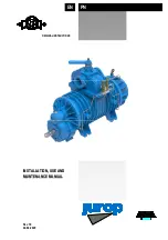
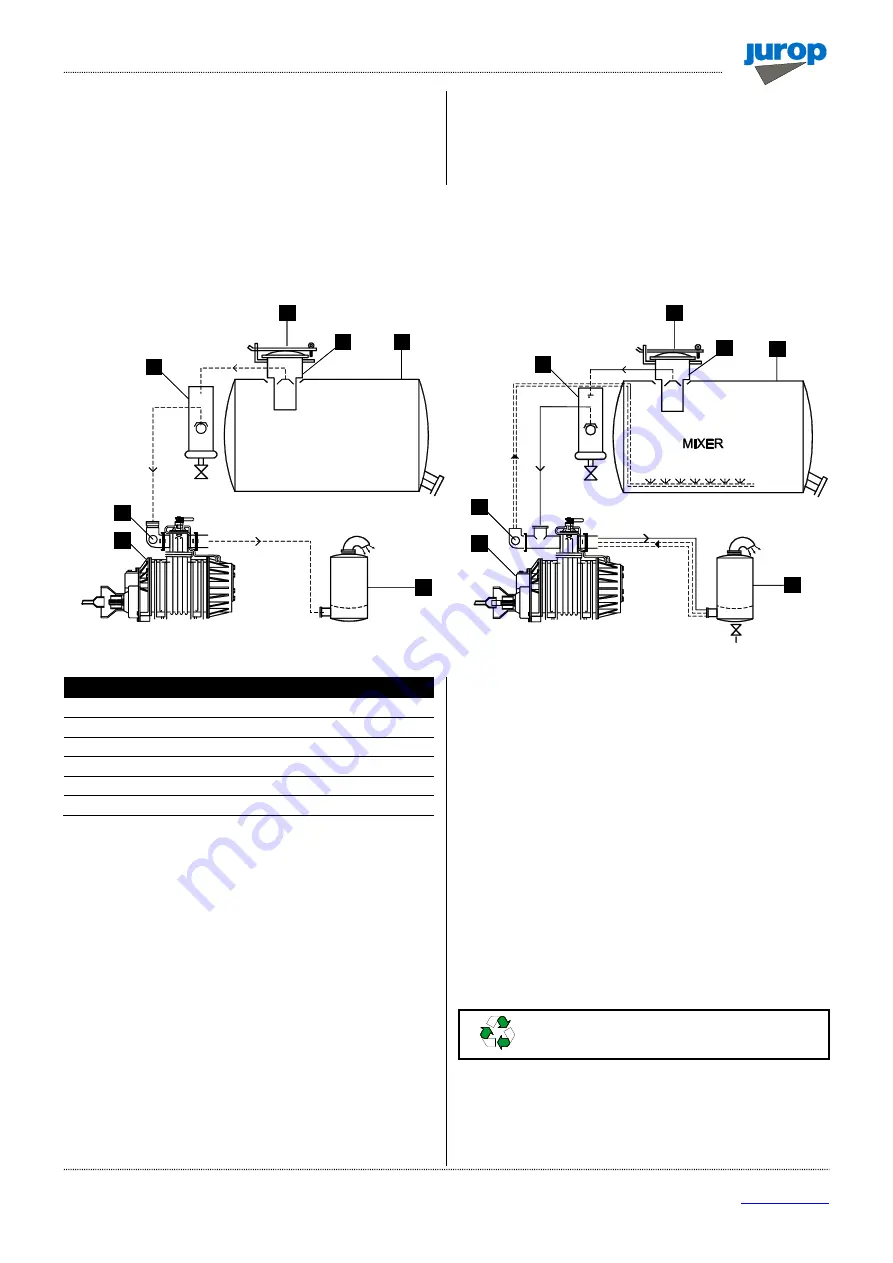
4.6. Vacuum / Pressure line
• See the following picture.
Pic. 4.2
Vacuum / Pressure line components
1
Primary shutoff
2
Tank
3
Secondary shutoff
4
Si oil trap
5
PN pump
6
Safety relief valve
• The hoses connecting the suction and exhaust ports of the
vacuum pump must be of adequate diameter (suggested not less than
3”) and of oil and corrosion resistant materials and before connecting
them, make sure that they are perfectly clean in the inside.
• The weight or dimensions of the pipes must in no way stress the
pump body. Use high temperature resistant rubber sleeves.
• Remove the port guards when mounting. The pipes and
components of the whole line must be clean.
• Avoid constrictions and tight curves where they are not essential.
• Connect the pump to the tank through the suction manifold which
has a threaded port for fitting the over-pressure valve.
• The exhaust pipes can reach high temperatures. Protect those
adequately from the operator reach.
• A non-return valve on suction pipe avoids rotation in the opposite
direction when the pump stops.
• To avoid that foreign liquids will enter the vacuum pump it is
necessary to mount on the suction line an over-flow valve of “floating-
ball” type (Fig. 4.2. - pos. 1). The flow section of this valve must be
equivalent to the suction hose’s one.
• It is also necessary to have on the line a suitable air filter for
preventing solids to be sucked inside the vacuum pump. It is also
recommended to mount a “secondary shutoff” of floating-ball type (Fig.
4.2 - pos. 3) between vacuum pump and over-flow (primary shutoff).
• Called also 4-way valve, normally is manually operated but it can
be at any time transformed in pneumatically or hydraulic operated upon
request of the appropriate kit.
• During normal running of the pump the resulting noise should be
reduced by means of a suitable silencer (Fig. 4.2 - pos. 4) mounted as
close as possible to the pump itself. It has to be dimensioned for the air
flow produced by the pump model. The oil used for the pump’s inside
lubrication has to be separated from the exhausted air by means of an
adequate oil-separator, placed directly inside the silencer. The silencer
is fitted also with a draining tap for the collected oil and condensed
liquids.
Do not dispose of in the environment. Dispose of
in compliance with the standards in force.
• Over-pressure safety relief valves (Pic. 4.2 - pos. 6). It must be
dimensioned to discharge the entire air-flow of the pump. The
adjustment of this valve has to be kept inside 10% of tolerance of the
pump's working pressure and in any case, it has to stay inside the
given value of the tank's work pressure.
3
5
4
6
1
2
5
6
4
3
2
6
6
1
PN PUMP WITH STANDARD MANIFOLD
PN PUMP WITH MIXER MANIFOLD